
Circuit Documentation
Summary of the Circuit
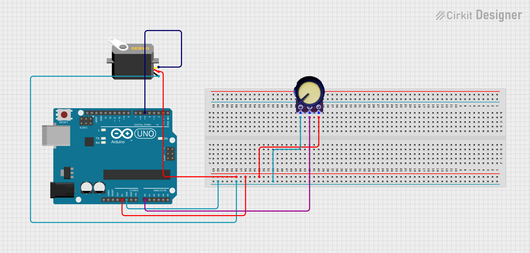
This circuit consists of an Arduino UNO microcontroller, a servo motor, and a potentiometer. The Arduino UNO is used as the central control unit, interfacing with the servo motor to control its position and with the potentiometer to receive analog input that can be used to determine the servo's position. The servo motor is powered by the Arduino and receives pulse width modulation (PWM) signals to set its angle. The potentiometer provides a variable resistance that is used to generate a corresponding voltage signal, which is read by the Arduino's analog input to determine the desired position of the servo.
Component List
Servo Motor
- Pins: gnd, vcc, pulse
- Description: A servo motor is an actuator that allows for precise control of angular position. It typically consists of a motor coupled to a sensor for position feedback.
Arduino UNO
- Pins: UNUSED, IOREF, Reset, 3.3V, 5V, GND, Vin, A0-A5, SCL, SDA, AREF, D0-D13
- Description: The Arduino UNO is a microcontroller board based on the ATmega328P. It has digital input/output pins, analog inputs, a USB connection for programming, and power management features.
Potentiometer
- Pins: GND, Output, VCC
- Description: A potentiometer is a three-terminal resistor with a sliding or rotating contact that forms an adjustable voltage divider. It can be used to control device parameters or as input devices.
Wiring Details
Servo Motor
- Ground (gnd): Connected to the ground (GND) of the Arduino UNO and the ground (GND) of the potentiometer.
- Power (vcc): Connected to the 5V output of the Arduino UNO and the VCC of the potentiometer.
- Control Signal (pulse): Connected to digital pin D5 of the Arduino UNO.
Arduino UNO
- Ground (GND): Connected to the ground (gnd) of the servo motor and the ground (GND) of the potentiometer.
- 5V: Provides power to the servo motor (vcc) and the potentiometer (VCC).
- Digital Pin D5: Outputs PWM signal to the servo motor (pulse).
- Analog Pin A0: Reads the voltage signal from the potentiometer (Output).
Potentiometer
- Ground (GND): Connected to the ground (GND) of the Arduino UNO and the ground (gnd) of the servo motor.
- Voltage Output (Output): Connected to analog pin A0 of the Arduino UNO.
- Power (VCC): Connected to the 5V output of the Arduino UNO.
Documented Code
Arduino UNO Code (sketch.ino)
void setup() {
  // put your setup code here, to run once:

}

void loop() {
  // put your main code here, to run repeatedly:

}
The provided code is a template with empty setup() and loop() functions. The setup() function is intended for initialization code that runs once at the start, such as pin mode configurations. The loop() function contains the main logic of the program, which runs repeatedly.
Additional Notes
- The code for the Arduino UNO is incomplete and requires implementation of the logic to read the potentiometer value from analog pin A0 and convert it to a servo position, which is then sent as a PWM signal to the servo motor via digital pin D5.
- The
documentation.txtfile is empty and does not contain any additional information.