Raspberry Pi Pico Controlled Bluetooth Robotic Vehicle with Ultrasonic Sensor and Servo Steering
Circuit Documentation
Summary
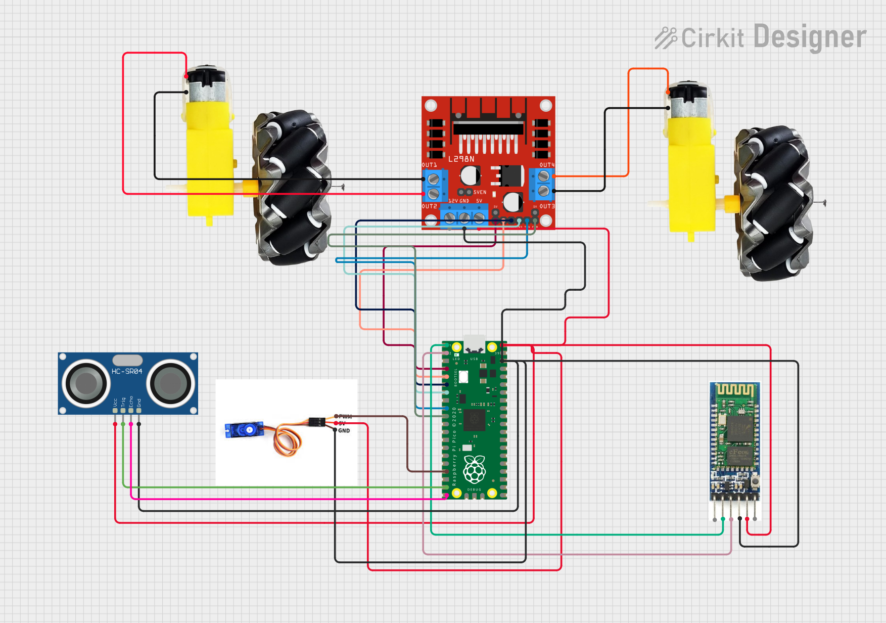
This circuit integrates a Raspberry Pi Pico microcontroller with a variety of peripherals including a Bluetooth module, an L298N DC motor driver, two sets of motors and wheels, an HC-SR04 Ultrasonic Sensor, and an SG90 servo motor. The Raspberry Pi Pico serves as the central processing unit, controlling the motors through the L298N driver, communicating via Bluetooth, and interfacing with the ultrasonic sensor and servo motor for sensing and actuation purposes.
Component List
Raspberry Pi Pico
- Microcontroller board based on the RP2040 microcontroller, featuring a dual-core ARM Cortex-M0+ processor and a rich set of I/O capabilities.
L298N DC Motor Driver
- A high-power motor driver capable of driving up to two DC motors, with direction and speed control via digital logic signals.
Bluetooth Module
- A wireless communication module that allows for Bluetooth connectivity, enabling remote control and data exchange with the microcontroller.
Motors and Wheels (2 sets)
- DC motors connected to wheels, providing the motion capability for a robotic platform or vehicle.
HC-SR04 Ultrasonic Sensor
- A distance measuring sensor that uses ultrasonic waves to determine the distance to an object.
SG90 Servo Motor
- A small and lightweight servo motor capable of precise angular positioning, commonly used for steering mechanisms or small robotic arms.
Wiring Details
Raspberry Pi Pico
- Bluetooth Module:
pin 1connected to Bluetooth module'sRXDpin 2connected to Bluetooth module'sTXD
- L298N DC Motor Driver:
pin 4connected toENApin 5connected toIN1pin 6connected toIN2pin 7connected toIN3pin 9connected toIN4pin 10connected toENB
- SG90 Servo Motor:
pin 17connected to Servo motor'sPWM
- HC-SR04 Ultrasonic Sensor:
pin 19connected toTRIGpin 20connected toECHO
- Common Connections:
pin 38connected to commonGNDpin 40connected to common5V
L298N DC Motor Driver
- Motors and Wheels:
OUT1connected to first motor'sGNDOUT2connected to first motor'sVCCOUT3connected to second motor'sGNDOUT4connected to second motor'sVCC
- Common Connections:
GNDconnected to commonGND5Vconnected to common5V
Bluetooth Module
- Power Connections:
vccconnected to common5Vgndconnected to commonGND
Motors and Wheels
- Each motor has two connections,
vccandGND, which are connected to the L298N motor driver's output channels.
HC-SR04 Ultrasonic Sensor
- Power Connections:
VCCconnected to common5VGNDconnected to commonGND
SG90 Servo Motor
- Power Connections:
5Vconnected to common5VGNDconnected to commonGND
Documented Code
Raspberry Pi Pico - sketch.ino
void setup() {
  // put your setup code here, to run once:

}

void loop() {
  // put your main code here, to run repeatedly:

}
Raspberry Pi Pico - documentation.txt
(No additional documentation provided for the code)
This concludes the documentation for the given circuit. The wiring details provide a clear overview of how each component is connected, and the code section provides the basic structure for the Raspberry Pi Pico's program. Additional code and comments would be necessary to implement the specific functionalities of the circuit.