Arduino-Controlled Dual Joystick Servo Manipulator
Circuit Documentation
Summary
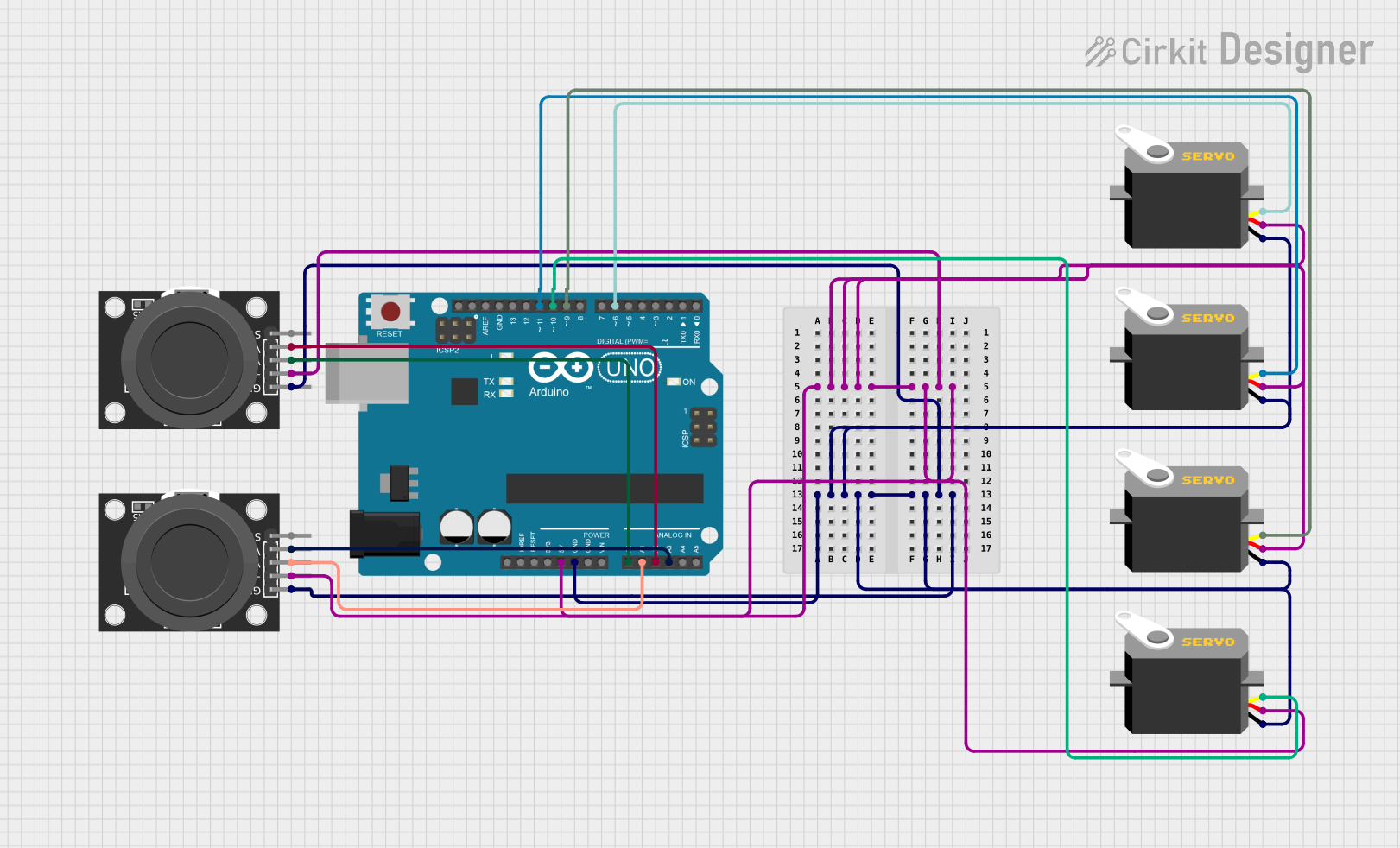
The circuit in question is designed to interface an Arduino UNO microcontroller with multiple servo motors and two KY-023 Dual Axis Joystick Modules. The servos are controlled by the Arduino, which receives input from the joystick modules to determine the position or motion of the servos. The circuit is powered by the Arduino's 5V output, which is distributed to both the joystick modules and the servo motors. Ground connections are also shared across all components.
Component List
Arduino UNO
- Microcontroller board based on the ATmega328P
- It has 14 digital input/output pins, 6 analog inputs, a 16 MHz quartz crystal, a USB connection, a power jack, an ICSP header, and a reset button.
KY-023 Dual Axis Joystick Module (x2)
- A module that provides two analog outputs (VRx and VRy) corresponding to the position of the joystick in two dimensions, and a digital output (SW) when the joystick is pressed down.
Servo Motor (x4)
- An actuator that can be precisely controlled for angular position, velocity, and acceleration. It has three connections: power (vcc), ground (gnd), and control signal (pulse).
Wiring Details
Arduino UNO
- 5V: Provides power to the servo motors and joystick modules.
- GND: Common ground for all components.
- A0: Connected to VRx of one joystick module.
- A1: Connected to VRx of the other joystick module.
- A2: Connected to VRy of one joystick module.
- A3: Connected to VRy of the other joystick module.
- D6, D9, D10, D11: Control signals connected to the pulse pins of the servo motors.
KY-023 Dual Axis Joystick Module
- GND: Connected to the common ground.
- +5V: Receives power from the Arduino's 5V output.
- VRx: Analog output connected to Arduino's analog input pins (A0 or A1).
- VRy: Analog output connected to Arduino's analog input pins (A2 or A3).
- SW: Not connected in this circuit.
Servo Motor
- gnd: Connected to the common ground.
- vcc: Receives power from the Arduino's 5V output.
- pulse: Receives control signal from Arduino's digital output pins (D6, D9, D10, D11).
Documented Code
void setup() {
  // put your setup code here, to run once:

}

void loop() {
  // put your main code here, to run repeatedly:

}
The provided code is a template and does not contain any functional code for controlling the servos or reading the joystick inputs. The setup() function is intended for initialization code that runs once, and the loop() function is for code that runs repeatedly, controlling the circuit's behavior. The user will need to add the specific code to read the joystick inputs and control the servo positions accordingly.