
Arduino UNO Controlled Touch-Activated LED and Buzzer System
View and Edit Project In Cirkit Designer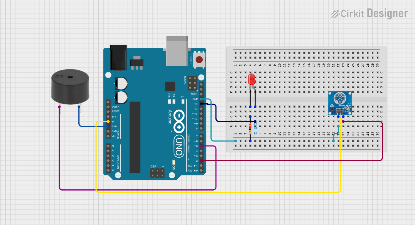
Circuit Documentation
Summary of the Circuit
This circuit appears to be designed for a simple interactive system that includes an LED, a touch sensor, a buzzer, and an Arduino UNO microcontroller. The LED is controlled by the Arduino and is likely to indicate the status or a response to the touch sensor input. The touch sensor provides input to the Arduino, which then processes the signal and can trigger the buzzer as an output. The circuit is powered by the Arduino's 5V output, and ground connections are shared among the components.
Component List
LED: Two Pin (red)
- Description: A red LED with two pins: anode and cathode.
- Purpose: To provide visual feedback or indication.
Touch Sensor
- Description: A sensor with three pins: IO, VCC, and GND.
- Purpose: To detect touch inputs and send signals to the microcontroller.
Arduino UNO
- Description: A microcontroller board with various digital and analog I/O pins.
- Purpose: To control the operation of the circuit, process inputs, and drive outputs.
Buzzer
- Description: An electromechanical component with two pins: PIN and GND.
- Purpose: To provide audible feedback or alerts.
Resistor (220 Ohms)
- Description: A passive two-pin component with a resistance of 220 Ohms.
- Purpose: To limit current through the LED, protecting it from damage.
Wiring Details
LED: Two Pin (red)
- Anode: Connected to the Arduino UNO's digital pin D13.
- Cathode: Connected to one pin of the 220 Ohm resistor.
Touch Sensor
- IO: Connected to the Arduino UNO's digital pin D2.
- VCC: Connected to the Arduino UNO's 5V power supply.
- GND: Connected to the Arduino UNO's ground (GND).
Arduino UNO
- D13: Connected to the anode of the LED.
- D2: Connected to the IO pin of the touch sensor.
- 5V: Provides power to the touch sensor.
- GND: Common ground for the touch sensor, buzzer, and resistor.
- D5: Connected to the PIN of the buzzer.
Buzzer
- PIN: Connected to the Arduino UNO's digital pin D5.
- GND: Connected to the Arduino UNO's ground (GND).
Resistor (220 Ohms)
- Pin1: Connected to the cathode of the LED.
- Pin2: Connected to the Arduino UNO's ground (GND).
Documented Code
Arduino UNO Code (sketch.ino)
void setup() {
  // put your setup code here, to run once:

}

void loop() {
  // put your main code here, to run repeatedly:

}
Note: The provided code is a template and does not contain any functional code. It needs to be filled in with the logic to control the LED and buzzer in response to the touch sensor input.