Cirkit Designer
Your all-in-one circuit design IDE
Home /
Project Documentation
74HC93-Based LED Counter with Pushbutton Control
Circuit Documentation
Summary
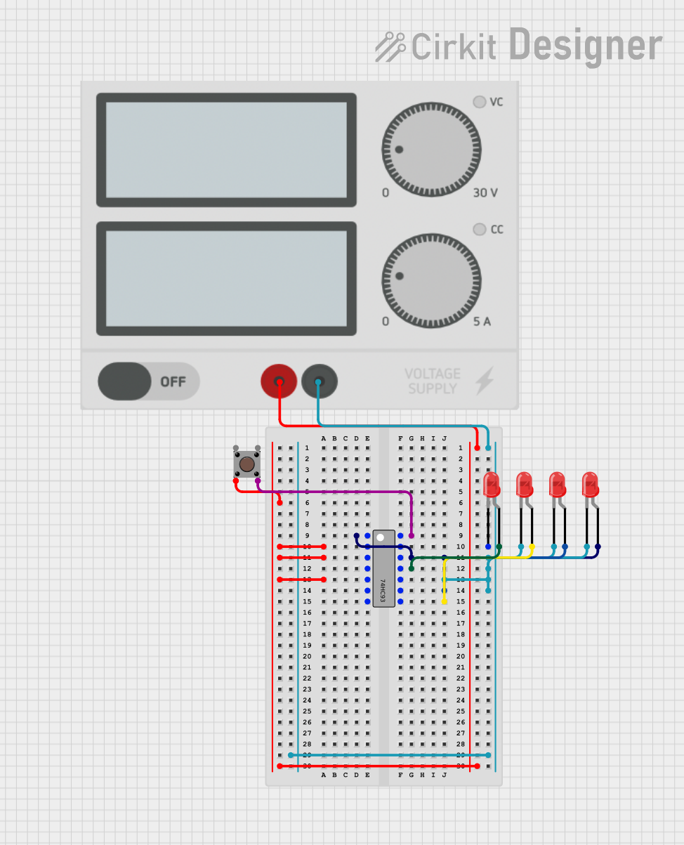
This circuit is a simple digital counter using a 74HC93 4-bit binary counter IC, a pushbutton for clock input, and four red LEDs to display the output. The circuit is powered by a power supply. The pushbutton is used to increment the counter, and the LEDs display the binary count.
Component List
- 74HC93: A 4-bit binary counter IC.
- Power Supply: Provides the necessary voltage and current to the circuit.
- Pushbutton: Used to provide clock pulses to the counter.
- LED: Two Pin (red): Used to display the binary output of the counter.
Wiring Details
74HC93
- Clock 1: Connected to Output 0 of the 74HC93 and anode of one LED.
- Reset 1: Connected to the positive terminal of the Power Supply.
- Reset 2: Connected to the positive terminal of the Power Supply.
- VCC: Connected to the positive terminal of the Power Supply.
- Clock 0: Connected to Pin 4 (out) of the Pushbutton.
- Output 0: Connected to Clock 1 of the 74HC93 and anode of one LED.
- Output 1: Connected to anode of one LED.
- Output 2: Connected to anode of one LED.
- Output 3: Connected to anode of one LED.
- GND: Connected to the negative terminal of the Power Supply and cathodes of all LEDs.
Power Supply
- +: Connected to Pin 2 (in) of the Pushbutton, Reset 1, Reset 2, and VCC of the 74HC93.
- -: Connected to GND of the 74HC93 and cathodes of all LEDs.
Pushbutton
- Pin 1 (in): Not connected.
- Pin 2 (in): Connected to the positive terminal of the Power Supply.
- Pin 3 (out): Not connected.
- Pin 4 (out): Connected to Clock 0 of the 74HC93.
LED: Two Pin (red)
- Anode:
- One LED anode connected to Output 0 of the 74HC93.
- One LED anode connected to Output 1 of the 74HC93.
- One LED anode connected to Output 2 of the 74HC93.
- One LED anode connected to Output 3 of the 74HC93.
- Cathode: All LED cathodes connected to the negative terminal of the Power Supply.
Code
There is no microcontroller code associated with this circuit.