
Arduino-Based GPS Speedometer with LCD Display and Relay Control
View and Edit Project In Cirkit Designer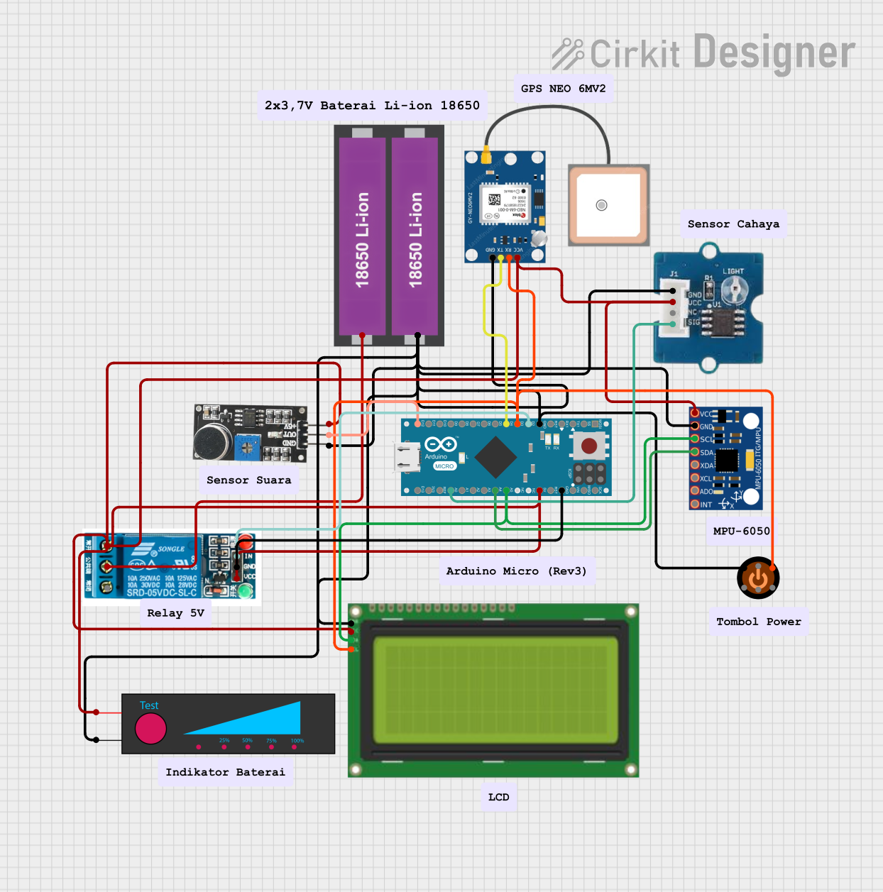
Circuit Documentation
Summary
This document provides a detailed overview of a circuit that integrates various sensors, a relay, an LCD display, and a GPS module, all controlled by an Arduino Micro (Rev3). The circuit is powered by two 18650 Li-ion batteries and includes components such as a light sensor, sound sensor, and MPU-6050 accelerometer and gyroscope. The Arduino Micro is programmed to read sensor data, control the relay, and display information on the LCD.
Component List
GPS NEO 6M
- Pins: VCC, RX, TX, GND
- Description: GPS module for location tracking.
MPU-6050
- Pins: VCC, GND, SCL, SDA, XDA, XCL, AD0, INT
- Description: Accelerometer and gyroscope sensor.
Lcd 20x4 i2c
- Pins: GND, 5V, SCA, SCL
- Description: 20x4 character LCD display with I2C interface.
Light Sensor
- Pins: GND, UCC, NC, SIG
- Description: Sensor to detect light intensity.
Arduino Micro (Rev3)
- Pins: MISO, 5V, SCK, MOSI, RESET, GND, RXLED/SS, D1/TX, D0/RX, D2/SDA, D3/SCL, D4 PWM/A6, D5 PWM, D6 PWM/A7, D7, D8 PWM/A8, D9 PWM/A9, D10 PWM/A10, D11 PWM, D12 PWM/A11, VIN, A5, A4, A3, A2, A1, A0, AREF, 3V3, D13 PWM
- Description: Microcontroller board based on the ATmega32U4.
18650 Li-ion Battery x 2
- Pins: +, -
- Description: Rechargeable lithium-ion batteries.
3104 Push Button
- Pins: pin 2, pin 5, pin 1, pin 3, pin 6, pin 4
- Description: Push button for user input.
Sound Sensor
- Pins: 5V +, OUT, GND
- Description: Sensor to detect sound levels.
5V Relay
- Pins: Normally Open, Common terminal, Normally Closed, In, GND, VCC
- Description: Relay module for switching high-power devices.
Battery Level
- Pins: +, -
- Description: Battery level indicator.
Wiring Details
GPS NEO 6M
- VCC connected to 5V (common power net)
- RX connected to D3/SCL on Arduino Micro
- TX connected to D4 PWM/A6 on Arduino Micro
- GND connected to GND (common ground net)
MPU-6050
- VCC connected to 5V (common power net)
- GND connected to GND (common ground net)
- SCL connected to A5 on Arduino Micro
- SDA connected to A4 on Arduino Micro
Lcd 20x4 i2c
- GND connected to GND (common ground net)
- 5V connected to 5V (common power net)
- SCA connected to A5 on Arduino Micro
- SCL connected to D3/SCL on Arduino Micro
Light Sensor
- GND connected to GND (common ground net)
- UCC connected to 5V (common power net)
- SIG connected to A0 on Arduino Micro
Arduino Micro (Rev3)
- 5V connected to 5V (common power net)
- GND connected to GND (common ground net)
- D2/SDA connected to In on 5V Relay
- D3/SCL connected to RX on GPS NEO 6M and SCL on Lcd 20x4 i2c
- D4 PWM/A6 connected to TX on GPS NEO 6M
- A5 connected to SCL on MPU-6050 and SCA on Lcd 20x4 i2c
- A4 connected to SDA on MPU-6050
- A0 connected to SIG on Light Sensor
- D12 PWM/A11 connected to OUT on Sound Sensor
18650 Li-ion Battery x 2
- + connected to Common terminal on 5V Relay
- - connected to GND (common ground net)
3104 Push Button
- pin 2 connected to RX on GPS NEO 6M
- pin 1 connected to GND (common ground net)
Sound Sensor
- 5V + connected to 5V (common power net)
- OUT connected to D12 PWM/A11 on Arduino Micro
- GND connected to GND (common ground net)
5V Relay
- Normally Open connected to 5V (common power net)
- Common terminal connected to + on 18650 Li-ion Battery x 2
- In connected to D2/SDA on Arduino Micro
- GND connected to GND (common ground net)
- VCC connected to 5V (common power net)
Battery Level
- + connected to 5V (common power net)
- - connected to GND (common ground net)
Code Documentation
Arduino Micro (Rev3) Code
const int buttonPin = 3; // Pin connected to the push button
const int relayPin = 2;  // Pin connected to the relay

bool relayState = false; // Current state of the relay
bool lastButtonState = LOW; // Previous state of the button
bool buttonPressed = false; // Flag to indicate if the button was pressed

void setup() {
  pinMode(buttonPin, INPUT);
  pinMode(relayPin, OUTPUT);
  digitalWrite(relayPin, LOW); // Ensure relay is off initially
}

void loop() {
  bool currentButtonState = digitalRead(buttonPin);

  // Check if the button is pressed
  if (currentButtonState == HIGH && lastButtonState == LOW) {
    buttonPressed = !buttonPressed; // Toggle the button pressed flag
  }

  // Update the relay state based on the button press
  if (buttonPressed) {
    relayState = !relayState; // Toggle the relay state
    digitalWrite(relayPin, relayState ? HIGH : LOW); // Update the relay output
    buttonPressed = false; // Reset the button pressed flag
  }

  lastButtonState = currentButtonState; // Update the last button state
}

#include <Wire.h>
#include <LiquidCrystal_I2C.h>
#include <TinyGPS++.h>
#include <SoftwareSerial.h>

// Initialize the LCD
LiquidCrystal_I2C lcd(0x27, 20, 4);

// Initialize the GPS
TinyGPSPlus gps;
SoftwareSerial ss(4, 3); // RX, TX

void setup() {
  lcd.begin();
  lcd.backlight();
  ss.begin(9600);
}

void loop() {
  while (ss.available() > 0) {
    gps.encode(ss.read());
    if (gps.speed.isUpdated()) {
      float speed = gps.speed.kmph();
      lcd.setCursor(0, 0);
      lcd.print("Speed: ");
      lcd.print(speed, 1); // Display speed with one decimal place
      lcd.print(" km/h");
    }
  }
}
This code initializes the Arduino Micro to read inputs from a push button and control a relay. It also sets up an LCD display and a GPS module to show the speed in km/h. The relay state is toggled based on the button press, and the GPS data is continuously read and displayed on the LCD.