
Arduino UNO-Based Motion Detection System with MPU-6050 and SIM800L for SMS Alerts
View and Edit Project In Cirkit Designer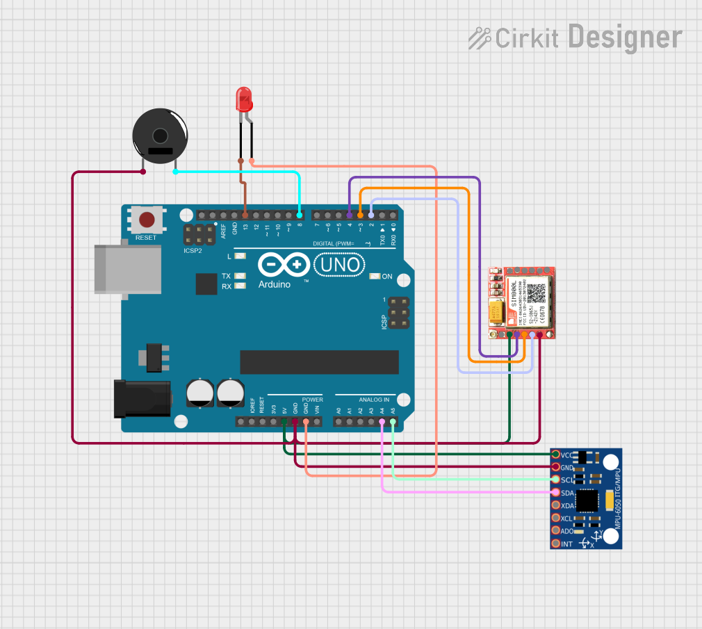
Circuit Documentation
Summary
This circuit integrates an Arduino UNO microcontroller with an MPU-6050 accelerometer and gyroscope, a SIM800L GSM module, a piezo buzzer, and a red LED. The Arduino UNO reads data from the MPU-6050 and sends SMS notifications via the SIM800L when specific conditions are met. The piezo buzzer and LED provide additional feedback.
Component List
Arduino UNO
- Description: A microcontroller board based on the ATmega328P.
- Pins: UNUSED, IOREF, Reset, 3.3V, 5V, GND, Vin, A0, A1, A2, A3, A4, A5, SCL, SDA, AREF, D13, D12, D11, D10, D9, D8, D7, D6, D5, D4, D3, D2, D1, D0
MPU-6050
- Description: A 6-axis motion tracking device that combines a 3-axis gyroscope and a 3-axis accelerometer.
- Pins: VCC, GND, SCL, SDA, XDA, XCL, AD0, INT
SIM800L
- Description: A GSM/GPRS module that allows for SMS, voice, and data communication.
- Pins: NFT, RING, VCC, DTR, RST, MIC +, RXD, MIC-, TXD, SPK+, GND, SPK-
Piezo Buzzer
- Description: An electronic device that produces a tone, alarm, or sound.
- Pins: pin 1, pin 2
LED: Two Pin (red)
- Description: A red light-emitting diode.
- Pins: cathode, anode
Wiring Details
Arduino UNO
5V connected to:
- MPU-6050 VCC
- SIM800L VCC
GND connected to:
- Piezo Buzzer pin 1
- MPU-6050 GND
- SIM800L GND
- LED anode
A4 connected to:
- MPU-6050 SDA
A5 connected to:
- MPU-6050 SCL
D13 connected to:
- LED cathode
D8 connected to:
- Piezo Buzzer pin 2
D4 connected to:
- SIM800L RST
D3 connected to:
- SIM800L RXD
D2 connected to:
- SIM800L TXD
MPU-6050
VCC connected to:
- Arduino UNO 5V
GND connected to:
- Arduino UNO GND
SDA connected to:
- Arduino UNO A4
SCL connected to:
- Arduino UNO A5
SIM800L
VCC connected to:
- Arduino UNO 5V
GND connected to:
- Arduino UNO GND
RST connected to:
- Arduino UNO D4
RXD connected to:
- Arduino UNO D3
TXD connected to:
- Arduino UNO D2
Piezo Buzzer
pin 1 connected to:
- Arduino UNO GND
pin 2 connected to:
- Arduino UNO D8
LED: Two Pin (red)
cathode connected to:
- Arduino UNO D13
anode connected to:
- Arduino UNO GND
Code Documentation
#include <Wire.h>
#include <MPU6050.h>
#include <SoftwareSerial.h>

MPU6050 mpu;
SoftwareSerial sim800(2, 3); // RX, TX
const int ledPin = 13;
const int threshold = 1000; // Adjust this threshold as needed

void setup() {
  pinMode(ledPin, OUTPUT);
  Wire.begin();
  Serial.begin(9600);
  sim800.begin(9600);
  mpu.initialize();
  if (!mpu.testConnection()) {
    Serial.println("MPU6050 connection failed");
    while (1);
  }
  Serial.println("MPU6050 connection successful");

  // Check SIM800L initialization
  sim800.print("AT\r");
  delay(100);
  if (sim800.available()) {
    String response = sim800.readString();
    if (response.indexOf("OK") == -1) {
      Serial.println("SIM800L initialization failed");
      while (1);
    }
  } else {
    Serial.println("SIM800L not responding");
    while (1);
  }

  sendSMS("System Initialized");
}

void loop() {
  int16_t ax, ay, az;
  mpu.getAcceleration(&ax, &ay, &az);
  int magnitude = sqrt(ax * ax + ay * ay + az * az);
  if (magnitude > threshold) {
    blinkLED();
    sendSMS("Movement detected!");
    delay(5000); // Wait 5 seconds before checking again
  }
  delay(100);
}

void blinkLED() {
  digitalWrite(ledPin, HIGH);
  delay(500);
  digitalWrite(ledPin, LOW);
  delay(500);
}

void sendSMS(const char* message) {
  sim800.print("AT+CMGF=1\r");
  delay(100);
  sim800.print("AT+CMGS=\"+1234567890\"\r"); // Replace with your phone number
  delay(100);
  sim800.print(message);
  delay(100);
  sim800.write(26); // ASCII code for CTRL+Z
  delay(1000); // Increased delay to ensure message is sent

  // Check if the message was sent successfully
  if (sim800.available()) {
    String response = sim800.readString();
    if (response.indexOf("OK") == -1) {
      Serial.println("Failed to send SMS");
    } else {
      Serial.println("SMS sent successfully");
    }
  } else {
    Serial.println("No response from SIM800L");
  }
}
This code initializes the MPU-6050 and SIM800L modules, reads acceleration data from the MPU-6050, and sends an SMS notification if the acceleration exceeds a specified threshold. The LED blinks to provide visual feedback, and the piezo buzzer can be used for audible alerts.