
Arduino UNO R4 WiFi Medical Data Gathering System with Heart Rate and Pulse Sensors
View and Edit Project In Cirkit Designer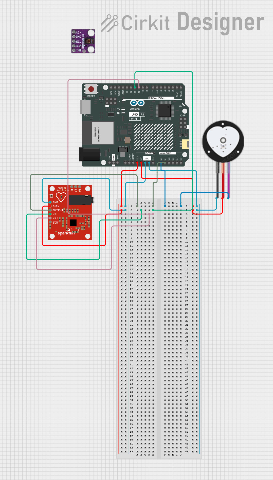
Circuit Documentation
Summary
This circuit is designed for medical data gathering using an Arduino UNO R4 WiFi microcontroller. It interfaces with a Heart Pulse Sensor and an AD8232 Heart Rate Monitor to collect and transmit heart rate data. The Heart Pulse Sensor's signal is read from an analog pin, while the AD8232 Heart Rate Monitor provides additional heart rate data through its output pin.
Component List
Arduino UNO R4 WiFi
- Description: A microcontroller board based on the ATmega328P, featuring built-in WiFi capabilities.
- Pins: OFF, GND, VRTC, IIC0_SCL, IIC0_SDA, 3V3, GPIO 41, GPIO 0, GPIO 42, GPIO 43, GPIO 44, BOOT, IOREF, RESET, 5V, VIN, A0, A1, A2, A3, A4, A5, RSPCKA, CIPO, COPI, D0/RX, D1/TX, D2, D3, D4, D5, D6, D7, D8, D9, D10, D11, D12, D13, AREF, SDA, SCL
max30100
- Description: A pulse oximeter and heart-rate sensor module.
- Pins: Vin, gnd, scl, sda, int
AD8232 Heart Rate Monitor
- Description: An integrated signal conditioning block for ECG and other biopotential measurement applications.
- Pins: GND, 3.3v, OUTPUT, LO-, LO+, SDN, RA, LA, RL
Heart Pulse Sensor
- Description: A sensor used to measure heart rate by detecting the pulse in the fingertip.
- Pins: GND, VCC, SIGNAL
Wiring Details
Arduino UNO R4 WiFi
- A1 connected to AD8232 Heart Rate Monitor OUTPUT
- A0 connected to Heart Pulse Sensor SIGNAL
- D11 connected to AD8232 Heart Rate Monitor LO-
- D10 connected to AD8232 Heart Rate Monitor LO+
- 3V3 connected to AD8232 Heart Rate Monitor 3.3v
- GND connected to AD8232 Heart Rate Monitor GND
- 5V connected to Heart Pulse Sensor VCC
- GND connected to Heart Pulse Sensor GND
AD8232 Heart Rate Monitor
- OUTPUT connected to Arduino UNO R4 WiFi A1
- LO- connected to Arduino UNO R4 WiFi D11
- LO+ connected to Arduino UNO R4 WiFi D10
- 3.3v connected to Arduino UNO R4 WiFi 3V3
- GND connected to Arduino UNO R4 WiFi GND
Heart Pulse Sensor
- SIGNAL connected to Arduino UNO R4 WiFi A0
- VCC connected to Arduino UNO R4 WiFi 5V
- GND connected to Arduino UNO R4 WiFi GND
Code Documentation
Arduino Sketch for Medical Data Gathering
/*
 * Arduino Sketch for Medical Data Gathering
 * This code interfaces with a Heart Pulse Sensor connected to the Arduino UNO R4 WiFi.
 * The sensor's signal is read from analog pin A0 and printed to the Serial Monitor.
 */

const int pulsePin = A0; // Pin connected to the pulse sensor signal

void setup() {
  Serial.begin(9600); // Initialize serial communication at 9600 baud
  pinMode(pulsePin, INPUT); // Set the pulse sensor pin as input
}

void loop() {
  int pulseValue = analogRead(pulsePin); // Read the analog value from the sensor
  Serial.println(pulseValue); // Print the pulse value to the Serial Monitor
  delay(1000); // Wait for 1 second before reading again
}
- File Name: sketch.ino
- Description: This Arduino sketch reads the analog value from the Heart Pulse Sensor connected to pin A0 and prints the value to the Serial Monitor every second.