Cirkit Designer
Your all-in-one circuit design IDE
Home /
Project Documentation
Arduino Nano-Controlled IR Sensor Water Pump System
Circuit Documentation
Summary of the Circuit
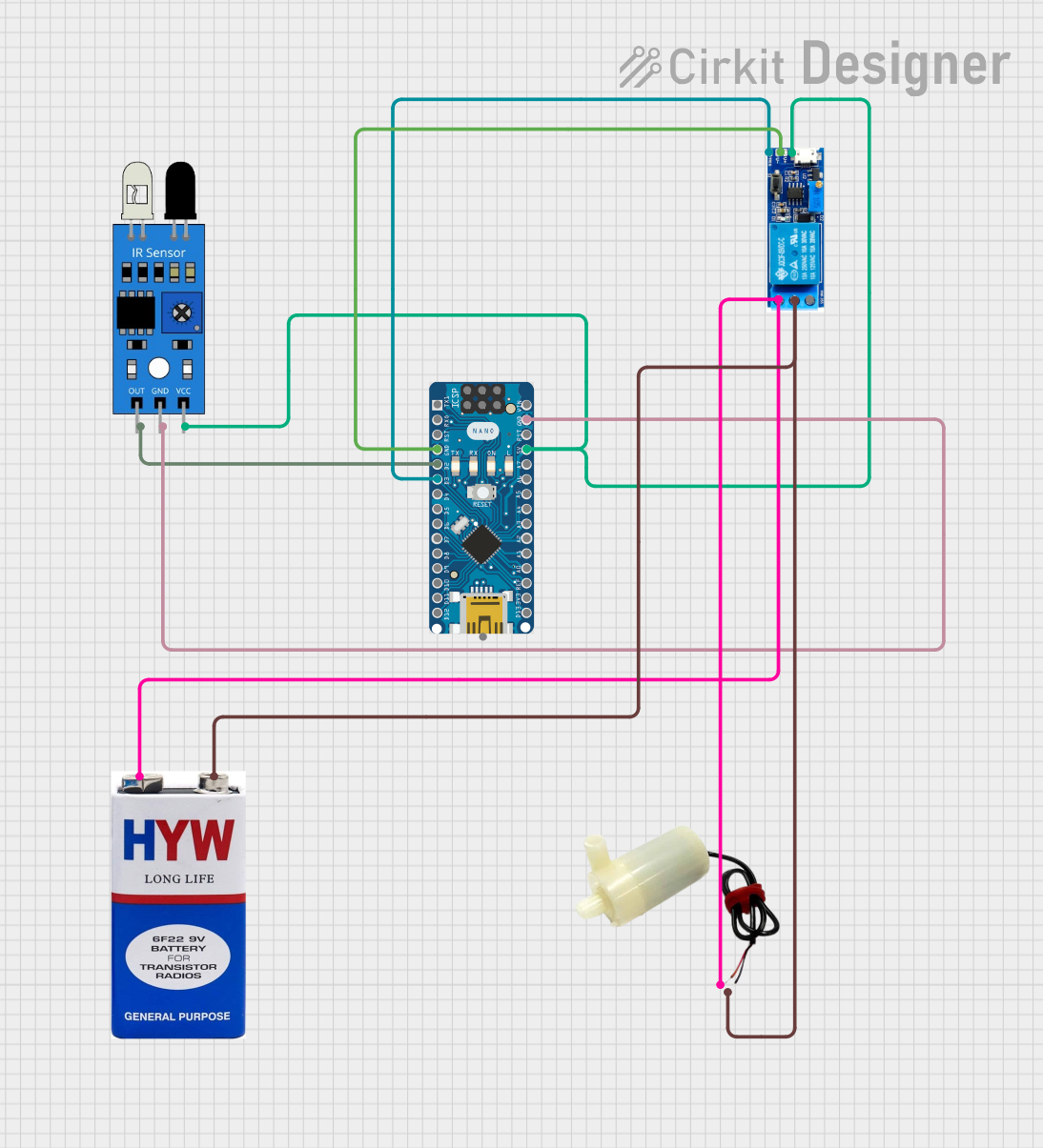
This circuit is designed to control a 5V mini water pump using an Arduino Nano microcontroller and an IR sensor. The IR sensor is used to detect the presence or absence of an object, and based on this input, the Arduino Nano controls the state of a relay module. The relay module then switches the water pump on or off. A 9V battery is used to provide power to the water pump, while the Arduino Nano and other components are powered by its 5V output.
Component List
Arduino Nano
- Description: A compact microcontroller board based on the ATmega328P.
- Purpose: Acts as the central processing unit of the circuit, reading sensor inputs and controlling the relay module.
5V Mini Water Pump
- Description: A small pump that operates at 5V for pumping water.
- Purpose: To pump water when activated by the relay module.
IR Sensor
- Description: An infrared sensor capable of detecting the presence of objects.
- Purpose: To provide input to the Arduino Nano for controlling the water pump.
Relay Module 5V-30V
- Description: An electromechanical switch that can be controlled by a low-power signal from the Arduino Nano.
- Purpose: To switch the water pump on or off without exposing the Arduino Nano to high currents.
9V Battery
- Description: A standard 9V battery.
- Purpose: To provide power to the water pump.
Wiring Details
Arduino Nano
- GND: Connected to the GND of the IR sensor and the V- of the Relay module.
- D2: Connected to the 'out' pin of the IR sensor.
- D3: Connected to the 'trigger' pin of the Relay module.
- 5V: Provides power to the VCC of the IR sensor and the V+ of the Relay module.
5V Mini Water Pump
- Positive Pin: Connected to the 'normally open' contact of the Relay module.
- Negative Pin: Connected to the 'common contact' of the Relay module.
IR Sensor
- Out: Connected to the D2 pin of the Arduino Nano.
- GND: Connected to the GND pin of the Arduino Nano.
- VCC: Powered by the 5V pin of the Arduino Nano.
Relay Module 5V-30V
- Common Contact: Connected to the negative pin of the 5V mini water pump and the negative terminal of the 9V battery.
- Normally Open: Connected to the positive pin of the 5V mini water pump and the positive terminal of the 9V battery.
- Normally Closed: Not connected in this circuit.
- Trigger: Controlled by the D3 pin of the Arduino Nano.
- V-: Connected to the GND pin of the Arduino Nano.
- V+: Powered by the 5V pin of the Arduino Nano.
9V Battery
- +: Connected to the 'normally open' contact of the Relay module.
- -: Connected to the 'common contact' of the Relay module.
Documented Code
Arduino Nano Code (sketch.ino)
void setup() {
  // put your setup code here, to run once:

}

void loop() {
  // put your main code here, to run repeatedly:

}
Note: The provided code is a template and does not contain any functional logic. It needs to be completed with the necessary setup and loop code to read the IR sensor and control the relay module.