ESP32-CAM Controlled Wi-Fi Robot Car

Circuit Documentation
Summary
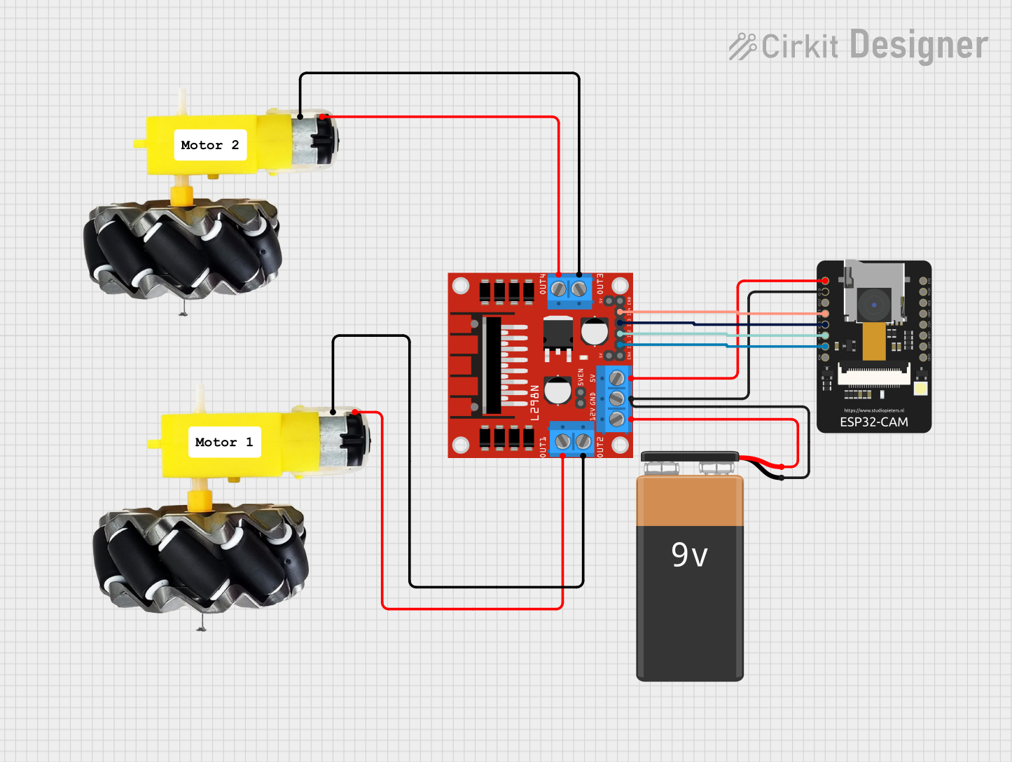
This circuit is designed to control a car with motorized wheels using an ESP32-CAM microcontroller. The ESP32-CAM is responsible for driving the motors through an L298N DC motor driver and for capturing images with its camera module. The car's movement can be controlled via a web server hosted on the ESP32-CAM, which provides a user interface with buttons for moving the car forward, backward, turning left, and right, as well as stopping the car. The circuit is powered by a 9V battery.
Component List
Motor and Wheels (x2)
- Description: These are the motorized wheels that propel the car. Each motor has two connections: VCC and GND.
ESP32-CAM
- Description: This is the microcontroller with Wi-Fi capability and a camera module. It controls the motor driver and handles the web server for remote control. It has multiple GPIO pins for interfacing with other components.
L298N DC Motor Driver
- Description: This component drives the motors based on signals from the ESP32-CAM. It has inputs for motor control signals and power, as well as outputs to the motors.
9V Battery
- Description: This is the power source for the circuit.
Comments (x2)
- Description: These are placeholders for additional notes or labels within the circuit design.
Wiring Details
Motor and Wheels
- VCC: Connected to the output pins (OUT1, OUT4) of the L298N motor driver.
- GND: Connected to the output pins (OUT2, OUT3) of the L298N motor driver.
ESP32-CAM
- 5V: Connected to the 5V input of the L298N motor driver.
- GND: Common ground with the 9V battery and the L298N motor driver.
- IO12, IO13, IO15, IO14, IO2, IO4: GPIO pins used for controlling the L298N motor driver.
- VOT, VOR, VCC, IO0, IO16, 3V3: Not connected in this circuit.
L298N DC Motor Driver
- OUT1, OUT2, OUT3, OUT4: Connected to the VCC and GND pins of the motor and wheels.
- 12V: Connected to the positive terminal of the 9V battery.
- GND: Common ground with the ESP32-CAM and the 9V battery.
- 5V: Connected to the 5V pin of the ESP32-CAM.
- 5V-ENA-JMP-I, 5V-ENA-JMP-O, +5V-J1, +5V-J2: Not connected in this circuit.
- ENA, IN1, IN2, IN3, IN4, ENB: Control inputs from the ESP32-CAM GPIO pins.
9V Battery
- +: Connected to the 12V input of the L298N motor driver.
- -: Common ground with the ESP32-CAM and the L298N motor driver.
Documented Code
/*
 * ESP32-CAM Car Control with Camera and WiFi
 * This code controls the L298N motor driver to drive the motors
 * connected to the car. The ESP32-CAM uses its GPIO pins to control
 * the direction and speed of the motors. Additionally, it initializes
 * the camera for capturing images and connects to a WiFi network.
 * It also sets up a web server with HTML buttons for controlling the car.
 */

#include "esp_camera.h"
#include <WiFi.h>
#include <WebServer.h>

// Define motor control pins
#define IN1 2
#define IN2 14
#define IN3 15
#define IN4 13

// Camera configuration
// ... (omitted for brevity)

// WiFi credentials
const char* ssid = "your_SSID";
const char* password = "your_PASSWORD";

WebServer server(80);

// Web server handlers for controlling the car
// ... (omitted for brevity)

void setup() {
  Serial.begin(115200);

  // Initialize motor control pins as outputs
  pinMode(IN1, OUTPUT);
  pinMode(IN2, OUTPUT);
  pinMode(IN3, OUTPUT);
  pinMode(IN4, OUTPUT);

  // Initialize camera
  // ... (omitted for brevity)

  // Connect to WiFi
  // ... (omitted for brevity)

  // Set up web server routes
  server.on("/", handleRoot);
  server.on("/forward", handleForward);
  server.on("/backward", handleBackward);
  server.on("/left", handleLeft);
  server.on("/right", handleRight);
  server.on("/stop", handleStop);
  server.begin();
  Serial.println("HTTP server started");
}

void loop() {
  server.handleClient();
}
Note: The code provided is a sketch for the ESP32-CAM microcontroller. It includes initialization of the camera module, WiFi connection setup, and web server configuration for remote control of the car. The actual motor control functions (handleForward, handleBackward, handleLeft, handleRight, handleStop) and camera configuration details have been omitted for brevity.