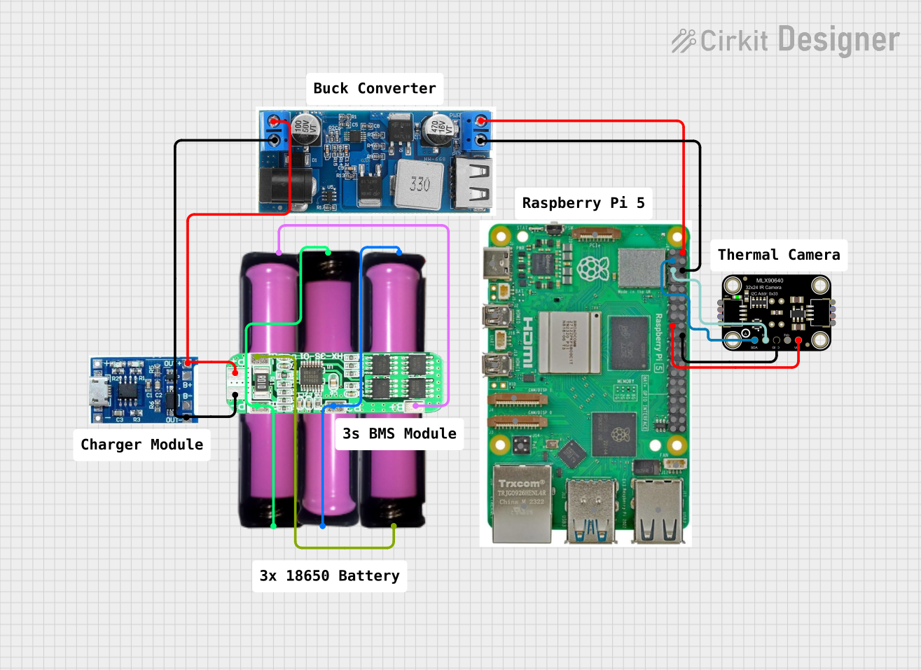
Raspberry Pi 5 and MLX90640 Thermal Camera Imaging System with Battery Backup

Circuit Documentation
Summary
This circuit is designed to interface a Raspberry Pi 5 with an Adafruit MLX90640 Thermal Camera, powered by a 24/12V buck converter and a 3S 10A Li-ion 18650 charger protection board module. The power is supplied by three 18650 batteries in holders, which are managed by the charger protection board and a lipo battery charger module. The Raspberry Pi 5 is responsible for processing the data from the thermal camera and is programmed to capture and output temperature readings from the camera's sensor array.
Component List
LiPo Battery Charger Module
A module designed to charge LiPo batteries, featuring input/output connections for the battery and the power supply.
Raspberry Pi 5
A powerful single-board computer with a variety of I/O options, including USB, Ethernet, HDMI, and a set of GPIO pins for interfacing with various peripherals like the Adafruit MLX90640 Thermal Camera.
Adafruit MLX90640 Thermal Camera
An infrared thermal camera that connects to the Raspberry Pi via I2C, capable of capturing temperature readings over an array of pixels.
24/12V Buck Converter
A voltage regulator that steps down the input voltage to a stable 5V output, used to power the Raspberry Pi 5.
18650 Battery in Holder
A rechargeable lithium-ion battery in a holder, providing power to the circuit. Three of these are used in the circuit.
3S 10A Li-ion 18650 Charger Protection Board Module
A protection module for the 18650 batteries, ensuring safe charging and discharging of the batteries.
Comments
Placeholder components that may represent annotations or notes within the circuit design, not physical parts.
Wiring Details
LiPo Battery Charger Module
- B-: Connected to the negative terminal of the battery.
- B+: Connected to the positive terminal of the battery.
- OUT-: Connected to the negative input of the buck converter and the P- of the charger protection board.
- OUT+: Connected to the positive input of the buck converter and the P+ of the charger protection board.
Raspberry Pi 5
- 5V: Receives power from the 5V output of the buck converter.
- GND: Common ground with the buck converter and the thermal camera.
- GPIO 2 (SDA): Connected to the SDA pin of the thermal camera for I2C data.
- GPIO 3 (SCL): Connected to the SCL pin of the thermal camera for I2C clock.
- 3.3V: Powers the thermal camera.
Adafruit MLX90640 Thermal Camera
- VCC: Powered by the 3.3V pin from the Raspberry Pi.
- GND: Common ground with the Raspberry Pi.
- SCL: Connected to GPIO 3 (SCL) on the Raspberry Pi for I2C clock.
- SDA: Connected to GPIO 2 (SDA) on the Raspberry Pi for I2C data.
24/12V Buck Converter
- VIN+: Connected to the P+ of the charger protection board.
- VIN-: Connected to the P- of the charger protection board.
- 5V: Powers the Raspberry Pi 5.
- GND: Common ground with the Raspberry Pi 5.
18650 Battery in Holder
- VCC: Connected to the B+ and B2 of the charger protection board.
- GND: Connected to the B- and B1 of the charger protection board.
3S 10A Li-ion 18650 Charger Protection Board Module
- B+: Connected to the positive terminal of one 18650 battery.
- B2: Connected to the positive terminal of the second 18650 battery.
- B1: Connected to the ground of the second and third 18650 batteries.
- P-: Connected to the negative input of the buck converter and the OUT- of the lipo battery charger module.
- P+: Connected to the positive input of the buck converter and the OUT+ of the lipo battery charger module.
- B-: Connected to the ground of the third 18650 battery.
Documented Code
#include <Wire.h>
#include <Adafruit_MLX90640.h>

Adafruit_MLX90640 mlx;

void setup() {
  Serial.begin(9600);
  while (!Serial); // Wait for Serial to be ready
  Serial.println("MLX90640 test");

  if (!mlx.begin()) {
    Serial.println("Failed to initialize MLX90640!");
    while (1);
  }
  Serial.println("MLX90640 initialized successfully");
}

void loop() {
  float mlx90640Frame[32 * 24]; // Buffer to store temperature readings

  // Capture the frame at the lowest resolution to increase the frame rate
  mlx.setMode(MLX90640_INTERLEAVED);

  // Request a frame capture
  if (mlx.getFrame(mlx90640Frame) == 0) {
    for (int i = 0; i < 24; i++) {
      for (int j = 0; j < 32; j++) {
        float temp = mlx90640Frame[i * 32 + j];
        Serial.print(temp);
        Serial.print(",");
      }
      Serial.println();
    }
  } else {
    Serial.println("Failed to read frame");
  }
  delay(1000); // Wait for 1 second before capturing next frame
}
This code is designed to run on the Raspberry Pi 5, which is interfaced with the Adafruit MLX90640 Thermal Camera. The code initializes the camera and continuously captures frames of thermal data, printing the temperature readings to the serial output.