
Arduino UNO-Based Multi-Button Interface with SD Card Logging and OLED Display
View and Edit Project In Cirkit Designer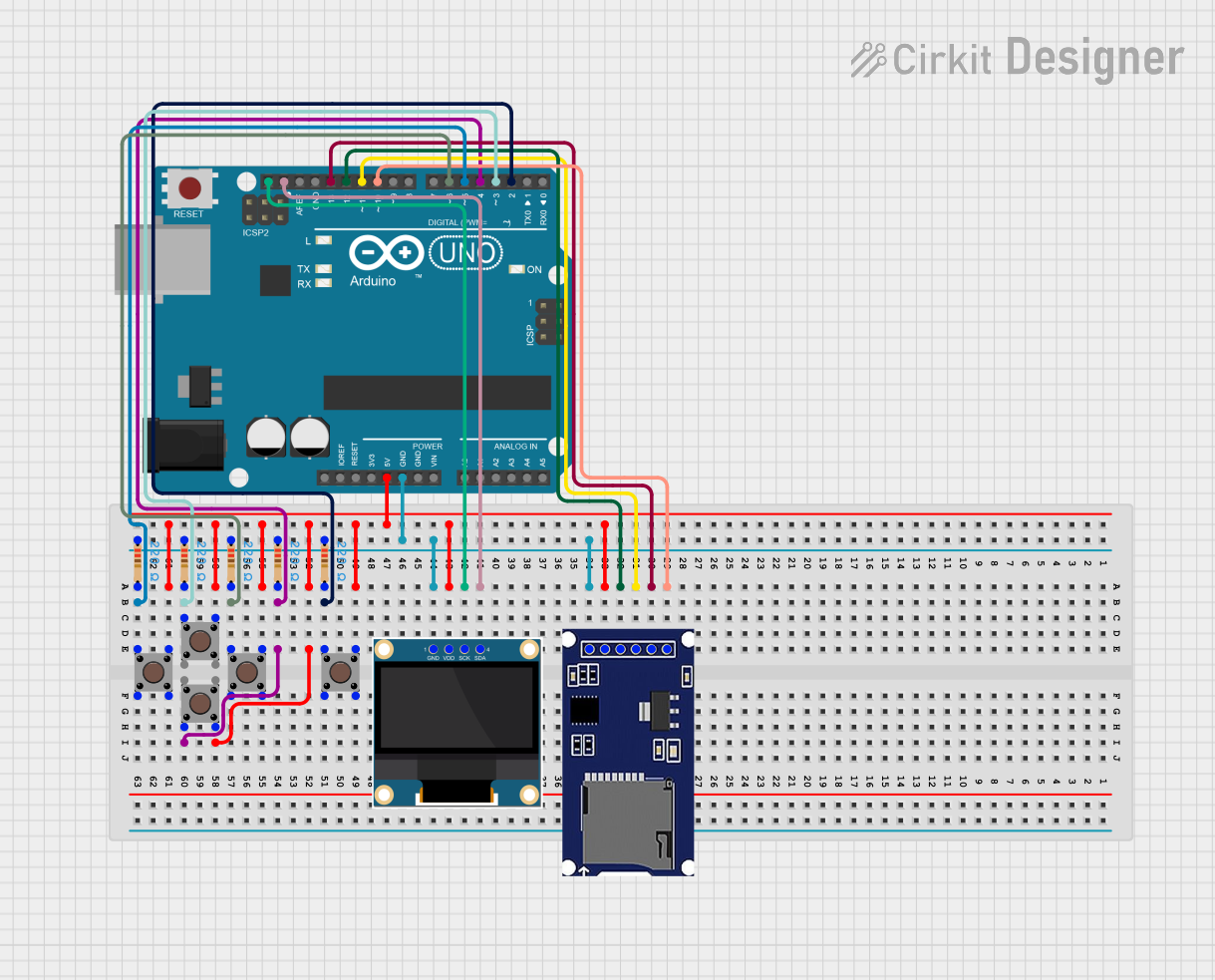
Circuit Documentation
Summary
This circuit involves an Arduino UNO microcontroller interfacing with an SD card module, a 0.96" OLED display, and multiple pushbuttons. The circuit is designed to read inputs from the pushbuttons and potentially display information on the OLED screen or store data on the SD card.
Component List
Arduino UNO
- Description: A microcontroller board based on the ATmega328P.
- Pins: UNUSED, IOREF, Reset, 3.3V, 5V, GND, Vin, A0, A1, A2, A3, A4, A5, SCL, SDA, AREF, D13, D12, D11, D10, D9, D8, D7, D6, D5, D4, D3, D2, D1, D0
Resistor
- Description: A passive electrical component that implements electrical resistance.
- Pins: pin1, pin2
- Properties: Resistance: 220 Ohms
Pushbutton
- Description: A simple switch mechanism for controlling some aspect of a machine or a process.
- Pins: Pin 3 (out), Pin 4 (out), Pin 1 (in), Pin 2 (in)
SD Module
- Description: A module for interfacing with SD cards.
- Pins: CS, SCK, MOSI, MISO, VCC, GND
0.96" OLED
- Description: A small OLED display module.
- Pins: GND, VDD, SCK, SDA
Wiring Details
Arduino UNO
- D10: Connected to SD Module (CS)
- D13: Connected to SD Module (SCK)
- D11: Connected to SD Module (MOSI)
- D12: Connected to SD Module (MISO)
- 5V: Connected to SD Module (VCC), 0.96" OLED (VDD), Pushbutton (Pin 3 (out)), Pushbutton (Pin 4 (out)), Pushbutton (Pin 3 (out)), Pushbutton (Pin 3 (out)), Pushbutton (Pin 3 (out))
- GND: Connected to SD Module (GND), Resistor (pin1), Resistor (pin1), Resistor (pin1), Resistor (pin1), Resistor (pin1), 0.96" OLED (GND)
- SDA: Connected to 0.96" OLED (SDA)
- SCL: Connected to 0.96" OLED (SCK)
- D2: Connected to Resistor (pin2), Pushbutton (Pin 1 (in))
- D4: Connected to Resistor (pin2), Pushbutton (Pin 2 (in))
- D6: Connected to Pushbutton (Pin 1 (in)), Resistor (pin2)
- D3: Connected to Pushbutton (Pin 1 (in)), Resistor (pin2)
- D5: Connected to Resistor (pin2), Pushbutton (Pin 1 (in))
Resistor
- pin1: Connected to SD Module (GND), Arduino UNO (GND)
- pin2: Connected to Pushbutton (Pin 1 (in)), Arduino UNO (D2)
- pin2: Connected to Pushbutton (Pin 2 (in)), Arduino UNO (D4)
- pin2: Connected to Pushbutton (Pin 1 (in)), Arduino UNO (D6)
- pin2: Connected to Pushbutton (Pin 1 (in)), Arduino UNO (D3)
- pin2: Connected to Pushbutton (Pin 1 (in)), Arduino UNO (D5)
Pushbutton
- Pin 3 (out): Connected to Arduino UNO (5V)
- Pin 4 (out): Connected to Arduino UNO (5V)
- Pin 1 (in): Connected to Resistor (pin2), Arduino UNO (D2)
- Pin 2 (in): Connected to Resistor (pin2), Arduino UNO (D4)
- Pin 1 (in): Connected to Resistor (pin2), Arduino UNO (D6)
- Pin 1 (in): Connected to Resistor (pin2), Arduino UNO (D3)
- Pin 1 (in): Connected to Resistor (pin2), Arduino UNO (D5)
SD Module
- CS: Connected to Arduino UNO (D10)
- SCK: Connected to Arduino UNO (D13)
- MOSI: Connected to Arduino UNO (D11)
- MISO: Connected to Arduino UNO (D12)
- VCC: Connected to Arduino UNO (5V)
- GND: Connected to Arduino UNO (GND)
0.96" OLED
- GND: Connected to Arduino UNO (GND)
- VDD: Connected to Arduino UNO (5V)
- SDA: Connected to Arduino UNO (SDA)
- SCK: Connected to Arduino UNO (SCL)
Documented Code
Arduino UNO Code
int select = 2;
int up = 3;
int down = 4;
int left = 5;
int right = 6;

void setup() {

}

void loop() {

}
This code initializes five integer variables corresponding to the digital pins connected to the pushbuttons. The setup and loop functions are currently empty, indicating that no specific functionality has been implemented yet.