
Circuit Documentation
Summary of the Circuit
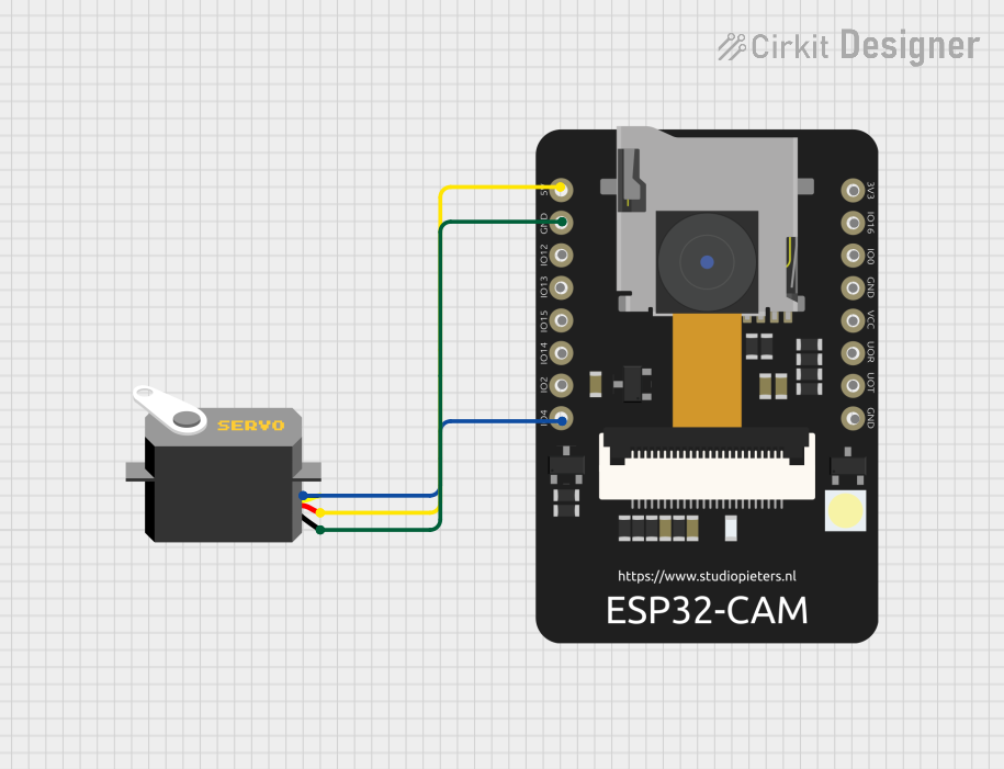
This circuit integrates an ESP32 CAM module with a servo motor. The ESP32 CAM is a small-sized camera module that can run independently or as a slave device to a host MCU. It is capable of performing image processing tasks and can be used for applications such as surveillance cameras, object recognition, and QR code scanning. The servo motor is controlled by the ESP32 CAM through one of its GPIO pins, allowing for precise angular movement or position control.
Component List
ESP32 CAM
- Description: A camera module with Wi-Fi and Bluetooth capabilities, suitable for image processing and IoT applications.
- Pins:
- 5V
- GND
- GPIO12
- GPIO13
- GPIO15
- GPIO14
- GPIO2
- GPIO4
- 3.3V
- GPIO16
- GPIO0
- 3.3V / 5V / P_OUT
- GPIO3 / RX
- GPIO1 / TX
Servo Motor
- Description: An actuator that can be precisely controlled for angular movement.
- Pins:
- gnd
- vcc
- pulse
Wiring Details
ESP32 CAM
- 5V: Connected to the VCC of the Servo Motor.
- GND: Connected to the GND of the Servo Motor.
- GPIO4: Connected to the pulse input of the Servo Motor to control its position.
Servo Motor
- vcc: Connected to the 5V output of the ESP32 CAM.
- gnd: Connected to the GND pin of the ESP32 CAM.
- pulse: Receives control signals from GPIO4 of the ESP32 CAM.
Documented Code
No code has been provided for the microcontrollers in the circuit. The documentation of the code would typically include a description of the functionality, setup and loop functions, and any functions or libraries used to control the servo motor and manage the camera module. Since no code is available, this section cannot be completed at this time.