Cirkit Designer
Your all-in-one circuit design IDE
Home /
Project Documentation
Arduino UNO-Based Environmental Monitoring System with LCD Display

Circuit Documentation
Summary
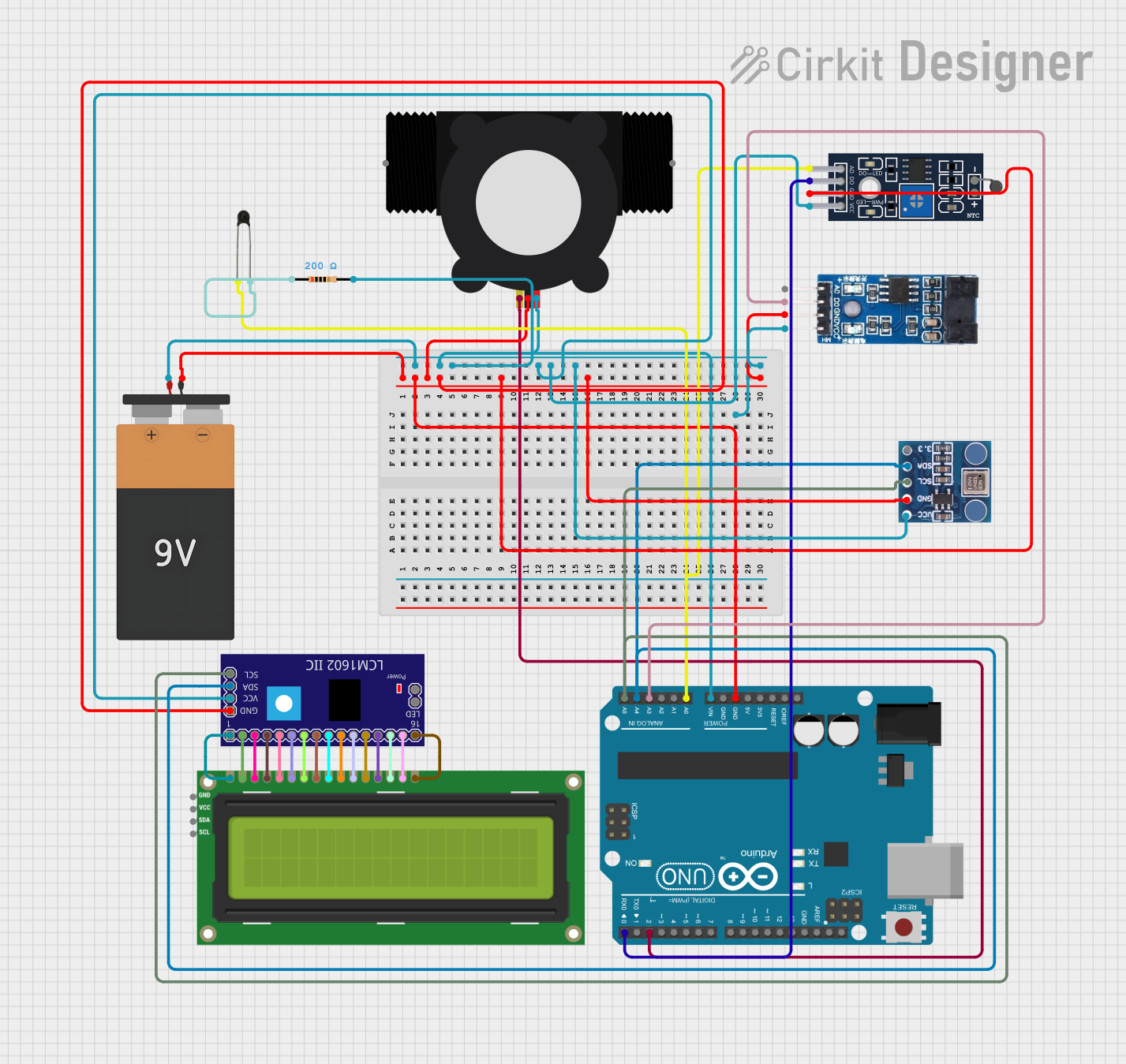
This document provides a detailed overview of a circuit designed to interface various sensors and modules with an Arduino UNO microcontroller. The circuit includes a power supply, a water flow meter, temperature sensors, a display module, and a barometric pressure sensor. The components are interconnected through a series of electrical nets, ensuring communication and power distribution across the system. The Arduino UNO serves as the central processing unit, running embedded code to control and monitor the connected devices.
Component List
Battery 9V
- Description: Provides the power supply for the circuit.
- Pins: VCC, GND
YF-S201 Water Flow Meter
- Description: Measures the flow rate of water passing through it.
- Pins: SIG, GND, VCC
LM393
- Description: A dual differential comparator that provides a digital signal output.
- Pins: VCC, GND, D0, A0
Sensor NTC LM393
- Description: A temperature sensor module that uses an NTC thermistor and an LM393 comparator.
- Pins: A0, D0, GND, VCC
NTC
- Description: A negative temperature coefficient thermistor used for temperature sensing.
- Pins: A0, A1
Arduino UNO
- Description: A microcontroller board based on the ATmega328P.
- Pins: UNUSED, IOREF, Reset, 3.3V, 5V, GND, Vin, A0-A5, SCL, SDA, AREF, D0-D13
I2C LCD 16x2 Screen
- Description: A liquid crystal display that can show 16 characters on 2 lines.
- Pins: SCL, SDA, VCC (5V), GND, VDD, VO, RS, RW, E, D0-D7, BLA, BLK
LCM1602 IIC
- Description: An I2C interface module for the 16x2 LCD screen.
- Pins: GND, VCC, SDA, SCL, D0-D7, A, K, VSS, VDD, V0, RS, RW, E, LED_A, LED_B
Resistor
- Description: A passive two-terminal electrical component that implements electrical resistance.
- Value: 200 Ohms
- Pins: pin1, pin2
BMP180
- Description: A digital barometric pressure sensor.
- Pins: 3.3, SDA, SCL, GND, VCC
Wiring Details
Battery 9V
- VCC connected to Arduino UNO Vin, YF-S201 Water Flow Meter VCC, Sensor NTC LM393 VCC, LCM1602 IIC VCC, BMP180 VCC, LM393 VCC through a 200 Ohm resistor.
- GND connected to Arduino UNO GND, YF-S201 Water Flow Meter GND, Sensor NTC LM393 GND, LCM1602 IIC GND, BMP180 GND, LM393 GND.
YF-S201 Water Flow Meter
- SIG connected to Arduino UNO D2.
- VCC connected to Battery 9V VCC.
- GND connected to Battery 9V GND.
LM393
- VCC connected to Battery 9V VCC.
- GND connected to Battery 9V GND.
- D0 connected to Arduino UNO A3.
- A0 not connected.
Sensor NTC LM393
- A0 connected to Arduino UNO A0 and NTC A0.
- D0 connected to Arduino UNO D0.
- VCC connected to Battery 9V VCC.
- GND connected to Battery 9V GND.
NTC
- A0 connected to Sensor NTC LM393 A0 and Arduino UNO A0.
- A1 connected to one end of the 200 Ohm resistor.
Arduino UNO
- GND connected to Battery 9V GND.
- Vin connected to Battery 9V VCC.
- A0 connected to Sensor NTC LM393 A0 and NTC A0.
- A1 not connected.
- A2 not connected.
- A3 connected to LM393 D0.
- A4 connected to BMP180 SDA and LCM1602 IIC SDA.
- A5 connected to BMP180 SCL and LCM1602 IIC SCL.
- D0 connected to Sensor NTC LM393 D0.
- D1-D13 not connected.
I2C LCD 16x2 Screen
- SCL connected to LCM1602 IIC SCL.
- SDA connected to LCM1602 IIC SDA.
- VCC (5V) connected to LCM1602 IIC VDD.
- GND connected to LCM1602 IIC VSS.
- VDD connected to LCM1602 IIC VDD.
- VO connected to LCM1602 IIC V0.
- RS connected to LCM1602 IIC RS.
- RW connected to LCM1602 IIC RW.
- E connected to LCM1602 IIC E.
- D0-D7 connected to LCM1602 IIC D0-D7 respectively.
- BLA connected to LCM1602 IIC A.
- BLK connected to LCM1602 IIC K.
LCM1602 IIC
- GND connected to Battery 9V GND.
- VCC connected to Battery 9V VCC.
- SDA connected to Arduino UNO A4 and BMP180 SDA.
- SCL connected to Arduino UNO A5 and BMP180 SCL.
- D0-D7 connected to I2C LCD 16x2 Screen D0-D7 respectively.
- A connected to I2C LCD 16x2 Screen BLA.
- K connected to I2C LCD 16x2 Screen BLK.
- VSS connected to I2C LCD 16x2 Screen GND.
- VDD connected to I2C LCD 16x2 Screen VDD.
- V0 connected to I2C LCD 16x2 Screen VO.
- RS connected to I2C LCD 16x2 Screen RS.
- RW connected to I2C LCD 16x2 Screen RW.
- E connected to I2C LCD 16x2 Screen E.
Resistor
- pin1 connected to NTC A1.
- pin2 connected to Battery 9V VCC.
BMP180
- 3.3 not connected.
- SDA connected to Arduino UNO A4 and LCM1602 IIC SDA.
- SCL connected to Arduino UNO A5 and LCM1602 IIC SCL.
- GND connected to Battery 9V GND.
- VCC connected to Battery 9V VCC.
Documented Code
Arduino UNO Code (sketch.ino)
void setup() {
  // put your setup code here, to run once:

}

void loop() {
  // put your main code here, to run repeatedly:

}
Additional Documentation (documentation.txt)
No additional documentation provided for the code.