
ESP32-Based Automated Water Pump System with RTC and Wi-Fi Control
View and Edit Project In Cirkit Designer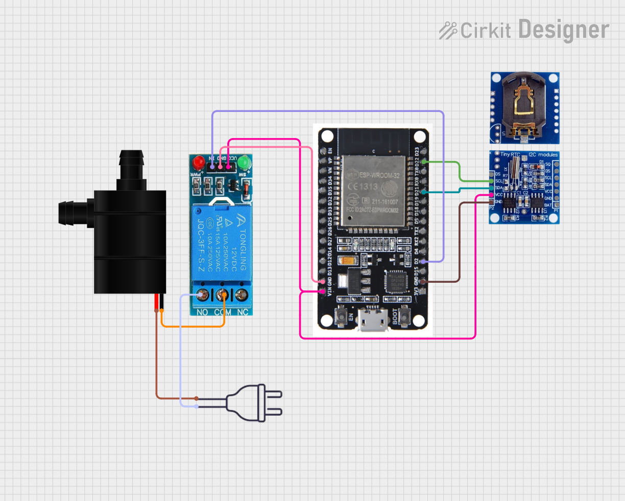
Circuit Documentation
Summary
This circuit is designed to control a water pump using an ESP32 microcontroller, an RTC DS1307 for timekeeping, and a 12V single-channel relay. The water pump is activated every 3 hours based on the RTC time. The system is integrated with Blynk for remote monitoring and control via WiFi.
Component List
Water Pump
- Description: A pump used to move water.
- Pins: VCC, GND
12V Single Channel Relay
- Description: A relay module used to control high voltage devices with a low voltage signal.
- Pins: NC, COM, NO, IN, GND, VCC
RTC DS1307
- Description: A real-time clock module used for timekeeping.
- Pins: DS, SCL, SDA, VCC, GND, SQ, BAT
ESP32
- Description: A microcontroller with WiFi and Bluetooth capabilities.
- Pins: EN, VP, VN, D34, D35, D32, D33, D25, D26, D27, D14, D12, D13, GND, VIN, 3V3, D15, D2, D4, RX2, TX2, D5, D18, D19, D21, RX0, TX0, D22, D23, BOOT
Power 220V
- Description: A power source providing 220V AC.
- Pins: Hot wire, Neutral wire
Wiring Details
Water Pump
- VCC connected to Hot wire of Power 220V
- GND connected to COM of 12V Single Channel Relay
12V Single Channel Relay
- COM connected to GND of Water Pump
- NO connected to Neutral wire of Power 220V
- IN connected to D2 of ESP32
- GND connected to GND of ESP32
- VCC connected to VIN of ESP32 and VCC of RTC DS1307
RTC DS1307
- SCL connected to D22 of ESP32
- SDA connected to D21 of ESP32
- VCC connected to VCC of 12V Single Channel Relay
- GND connected to GND of ESP32
ESP32
- D2 connected to IN of 12V Single Channel Relay
- GND connected to GND of 12V Single Channel Relay and GND of RTC DS1307
- VIN connected to VCC of 12V Single Channel Relay
- D22 connected to SCL of RTC DS1307
- D21 connected to SDA of RTC DS1307
Code Documentation
/*
 * This Arduino Sketch is designed to control a water pump using an ESP32, RTC DS1307,
 * and a 12V single channel relay. The pump is turned on every 3 hours based on the
 * RTC time. The system is also integrated with Blynk for remote monitoring and
 * control via WiFi.
 */

#define BLYNK_TEMPLATE_ID "TMPL6ijEa7EZW"
#define BLYNK_TEMPLATE_NAME "Penyiraman Otomatis"
#define BLYNK_AUTH_TOKEN "Lf9ZwWDPa6ZOWFbzGO_kKnllRtM4HUwg"

#include <Wire.h>
#include <RTClib.h>
#include <WiFi.h>
#include <BlynkSimpleEsp32.h>

// Blynk Auth Token
char auth[] = "YourAuthToken";

// Your WiFi credentials.
char ssid[] = "Kost Pink";
char pass[] = "Rumahkami12345678";

RTC_DS1307 rtc;

// Relay pin
const int relayPin = 2;

// Time interval for pump activation (3 hours in seconds)
const unsigned long interval = 3 * 60 * 60;
unsigned long previousMillis = 0;

void setup() {
  // Initialize serial communication
  Serial.begin(115200);

  // Initialize Blynk
  Blynk.begin(auth, ssid, pass);

  // Initialize RTC
  if (!rtc.begin()) {
    Serial.println("Couldn't find RTC");
    while (1);
  }

  if (!rtc.isrunning()) {
    Serial.println("RTC is NOT running!");
    // Set the RTC to the current date and time
    rtc.adjust(DateTime(F(__DATE__), F(__TIME__)));
  }

  // Initialize relay pin
  pinMode(relayPin, OUTPUT);
  digitalWrite(relayPin, LOW);
}

void loop() {
  // Run Blynk
  Blynk.run();

  // Get current time
  DateTime now = rtc.now();

  // Calculate elapsed time
  unsigned long currentMillis = now.unixtime();
  if (currentMillis - previousMillis >= interval) {
    // Save the last time the pump was turned on
    previousMillis = currentMillis;

    // Turn on the pump
    digitalWrite(relayPin, HIGH);
    delay(10000); // Pump runs for 10 seconds
    digitalWrite(relayPin, LOW);
  }
}
This code initializes the ESP32, connects to WiFi using Blynk, and sets up the RTC DS1307. The main loop checks the current time and activates the water pump every 3 hours for 10 seconds.