
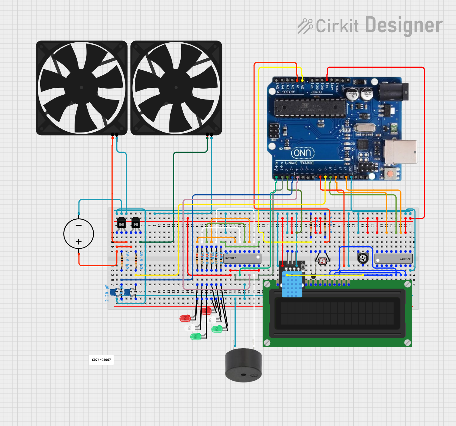
Circuit Documentation
Summary
This document provides a detailed overview of a circuit designed to interface various components including an LCD display, resistors, photocells (LDR), DHT11 sensor, LEDs, NPN transistors, capacitors, a fan, a shift register (74HC595), a buzzer, a DC power source, a trimmer potentiometer, and an Arduino Uno R3. The circuit appears to be a multifunctional system capable of sensing environmental conditions, displaying information, and controlling peripheral devices such as fans and LEDs.
Component List
LCD Display (16 pin)
- Description: A 16-pin liquid crystal display for showing alphanumeric characters.
- Pins: VSS, VDD, VO, RS, R_W, E, DB0-DB7, A, K
Resistor
- Description: A passive two-terminal electrical component that implements electrical resistance as a circuit element.
- Properties: Various resistance values (1000 Ohms, 10000 Ohms, 220 Ohms)
Photocell (LDR)
- Description: A light-dependent resistor whose resistance decreases with increasing incident light intensity.
DHT11
- Description: A basic, ultra low-cost digital temperature and humidity sensor.
LED: Two Pin (red, green, white)
- Description: Light Emitting Diodes of different colors used as indicators.
NPN Transistor (EBC)
- Description: A type of bipolar junction transistor used for amplification and switching.
Ceramic Capacitor
- Description: A fixed-value capacitor where the ceramic material acts as the dielectric.
- Properties: Capacitance value of 0.0000022 Farads
Fan
- Description: An electric fan for cooling purposes.
74HC595
- Description: An 8-bit shift register with a storage register and 3-state outputs.
Buzzer
- Description: An electronic buzzer for audible signaling.
DC Power Source
- Description: A source of direct current electricity.
Trimmer Potentiometer
- Description: A three-terminal resistor with an adjustable center tap.
Arduino Uno R3
- Description: A microcontroller board based on the ATmega328P.
NTC
- Description: A negative temperature coefficient thermistor used for temperature sensing.
Wiring Details
LCD Display (16 pin)
- VSS: Connected to ground.
- VDD: Connected to positive voltage supply.
- VO: Connected to the wiper of the trimmer potentiometer.
- RS, E, DB4-DB7: Controlled by the 74HC595 shift register.
- A: Connected to an Arduino Uno R3 digital pin for backlight control.
- K: Connected to ground.
Resistor
- Various resistors are used throughout the circuit for current limiting and voltage division.
Photocell (LDR)
- One side connected to a resistor forming a voltage divider, the other side to an Arduino Uno R3 analog input.
DHT11
- Signal pin connected to an Arduino Uno R3 digital pin.
- Power and ground pins connected to the respective supply rails.
LEDs (red, green, white)
- Anode connected to a resistor, and cathode connected to ground.
- Controlled via the 74HC595 shift register or directly by the Arduino Uno R3.
NPN Transistor (EBC)
- Emitter connected to the positive voltage supply.
- Collector connected to the fan's voltage input.
- Base connected to a resistor which is then connected to an Arduino Uno R3 digital pin for control.
Ceramic Capacitor
- Connected across the power supply lines near the fans for decoupling.
Fan
- Power connected to the collector of an NPN transistor.
- Ground connected to the ground rail.
74HC595
- Data, clock, and latch pins controlled by Arduino Uno R3 digital pins.
- Output enable tied to ground.
- Master reset connected to the positive voltage supply.
- Outputs Q0-Q7 connected to various components for control.
Buzzer
- One pin connected to the output of a 74HC595 shift register.
- The other pin connected to ground.
DC Power Source
- Provides the voltage supply for the circuit.
Trimmer Potentiometer
- Used to adjust the contrast of the LCD display.
Arduino Uno R3
- Controls the LCD display, reads sensors, drives the 74HC595 shift register, and interfaces with other components.
NTC
- Connected in a voltage divider configuration with a resistor to an Arduino Uno R3 analog input for temperature sensing.
Documented Code
There is no code provided for the microcontrollers in the circuit. The code would typically initialize the components, read sensor values, control outputs based on sensor inputs, and manage communication between the Arduino and other components such as the LCD display and shift registers.