Arduino-Controlled Laser Security System with LDR and Buzzer
Circuit Documentation
Summary
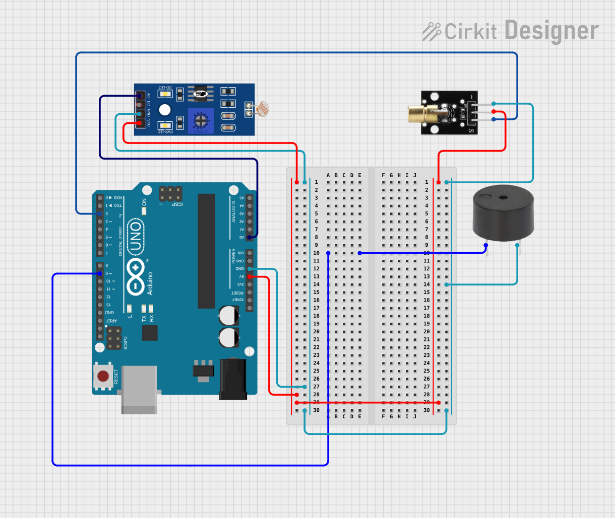
The circuit in question is designed to interface an LDR (Light Dependent Resistor) and a KY-008 Laser Emitter with an Arduino UNO microcontroller. Additionally, a buzzer is included in the circuit. The LDR is used to detect the intensity of light, the KY-008 Laser Emitter is used to emit a laser beam, and the buzzer is used to produce an audible alert. The Arduino UNO serves as the central processing unit, controlling the laser emitter and reading the LDR's value, as well as driving the buzzer.
Component List
LDR (Light Dependent Resistor)
- Pins: A0, D0, GND, VCC
- Description: A sensor that changes its resistance based on the light intensity.
KY-008 Laser Emitter
- Pins: SIG, 5V, GND
- Description: A module that emits a laser when powered.
Buzzer
- Pins: PIN, GND
- Description: An electromechanical component that produces an audible tone when powered.
Arduino UNO
- Pins: UNUSED, IOREF, Reset, 3.3V, 5V, GND, Vin, A0-A5, SCL, SDA, AREF, D0-D13
- Description: A microcontroller board based on the ATmega328P, with digital and analog I/O pins.
Wiring Details
LDR
- A0 connected to Arduino UNO A0
- GND connected to common ground
- VCC connected to Arduino UNO 5V
KY-008 Laser Emitter
- SIG connected to Arduino UNO D2
- 5V connected to Arduino UNO 5V
- GND connected to common ground
Buzzer
- PIN connected to Arduino UNO D9
- GND connected to common ground
Arduino UNO
- A0 connected to LDR A0
- D2 connected to KY-008 Laser Emitter SIG
- D9 connected to Buzzer PIN
- 5V connected to LDR VCC and KY-008 Laser Emitter 5V
- GND connected to common ground for LDR, KY-008 Laser Emitter, and Buzzer
Documented Code
Arduino UNO Code (sketch.ino)
void setup() {
  // put your setup code here, to run once:

}

void loop() {
  // put your main code here, to run repeatedly:

}
The provided code is a template with empty setup() and loop() functions, which are the entry points for Arduino code. The setup() function is called once when the program starts and is used to initialize settings, while the loop() function is called repeatedly and contains the main logic of the program. The actual implementation details would be added to these functions based on the desired behavior of the circuit.