Arduino-Controlled Automated Water Quality Monitoring and Pump Management System
Circuit Documentation
Summary
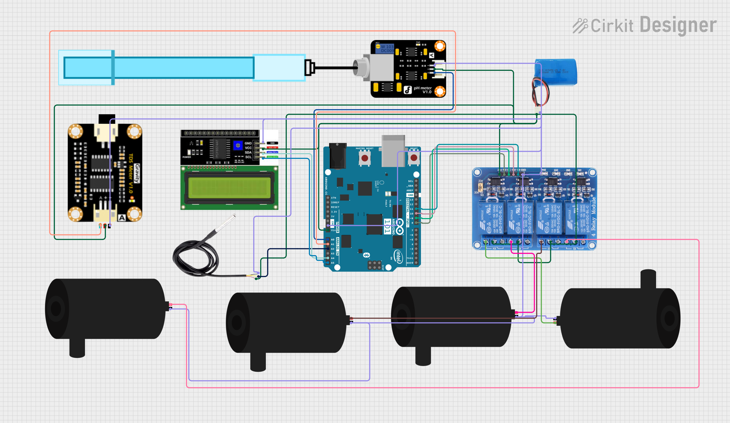
This circuit is designed to interface an Arduino 101 microcontroller with various sensors and actuators for monitoring and controlling an environment. The circuit includes temperature sensing (DS18B20), pH level measurement (PH Meter), Total Dissolved Solids (TDS) measurement (TDS Sensor Module), and an LCD I2C Display for output. It also controls multiple water pumps through a 4-channel relay module, which is powered by a 5V battery. The Arduino 101 serves as the central processing unit, reading sensor data and controlling the water pumps based on predefined conditions.
Component List
Arduino 101
- Microcontroller board based on the Intel Curie
- Provides I/O pins for interfacing with sensors, actuators, and displays
DS18B20
- Digital temperature sensor
- Provides temperature readings in a digital format
LCD I2C Display
- Alphanumeric liquid crystal display
- Uses I2C communication for displaying information
PH Meter
- Sensor for measuring the pH level of a solution
- Outputs an analog signal corresponding to the pH level
TDS Sensor Module
- Sensor for measuring Total Dissolved Solids in water
- Outputs an analog signal corresponding to the TDS level
Water Pump
- Electric pump for moving water
- Controlled by the relay module
Relay 4 Channel 5v
- 4-channel relay module for controlling high power devices
- Each channel can be controlled independently
5v Battery
- Power source for the relay module and other 5V components
Wiring Details
Arduino 101
A5/SCLconnected to LCD I2C DisplaySCLA4/SDAconnected to LCD I2C DisplaySDAA0connected to PH MeterSignalA1connected to TDS Sensor ModuleTDS AA2connected to DS18B20signalD11 PWM/MOSIconnected to Relay 4 Channel 5vIN1D10 PWM/SSconnected to Relay 4 Channel 5vIN2D9 PWMconnected to Relay 4 Channel 5vIN3D8connected to Relay 4 Channel 5vIN4GNDconnected to common ground netVINconnected to 5v batterypositiveand Relay 4 Channel 5vVCC
DS18B20
signalconnected to Arduino 101A2GNDconnected to common ground netvccconnected to 5v power net
LCD I2C Display
GNDconnected to common ground netVCCconnected to 5v power netSDAconnected to Arduino 101A4/SDASCLconnected to Arduino 101A5/SCL
PH Meter
Signalconnected to Arduino 101A0VCCconnected to 5v power netGNDconnected to common ground net
TDS Sensor Module
TDS Negativeconnected to common ground netTDS Positiveconnected to 5v power netTDS Aconnected to Arduino 101A1
Water Pump
positiveconnected to Relay 4 Channel 5vNOx(where x is the channel number 1-4)negativeconnected to common ground net
Relay 4 Channel 5v
GNDconnected to common ground netIN1toIN4connected to Arduino 101D11toD8VCCconnected to 5v power netCOM1toCOM4connected to 5v power netNO1toNO4connected to respective water pumppositive
5v Battery
positiveconnected to 5v power netnegativeconnected to common ground net
Documented Code
No code was provided for the microcontrollers in the circuit. The expected code should handle reading sensor data from the analog pins, processing the data, and controlling the relay module to turn the water pumps on or off based on the sensor readings. Additionally, the code should handle communication with the LCD I2C Display to output the sensor data or system status messages.
Please note that the actual implementation of the code would be necessary to provide a complete documentation of the system's functionality. The code would typically include initialization of the I2C communication, analog pin setup, main control loop with sensor reading and pump control logic, and functions for displaying data on the LCD.