ESP32-Controlled Traffic Light and Multi-Motor Driver System

Circuit Documentation
Summary of the Circuit
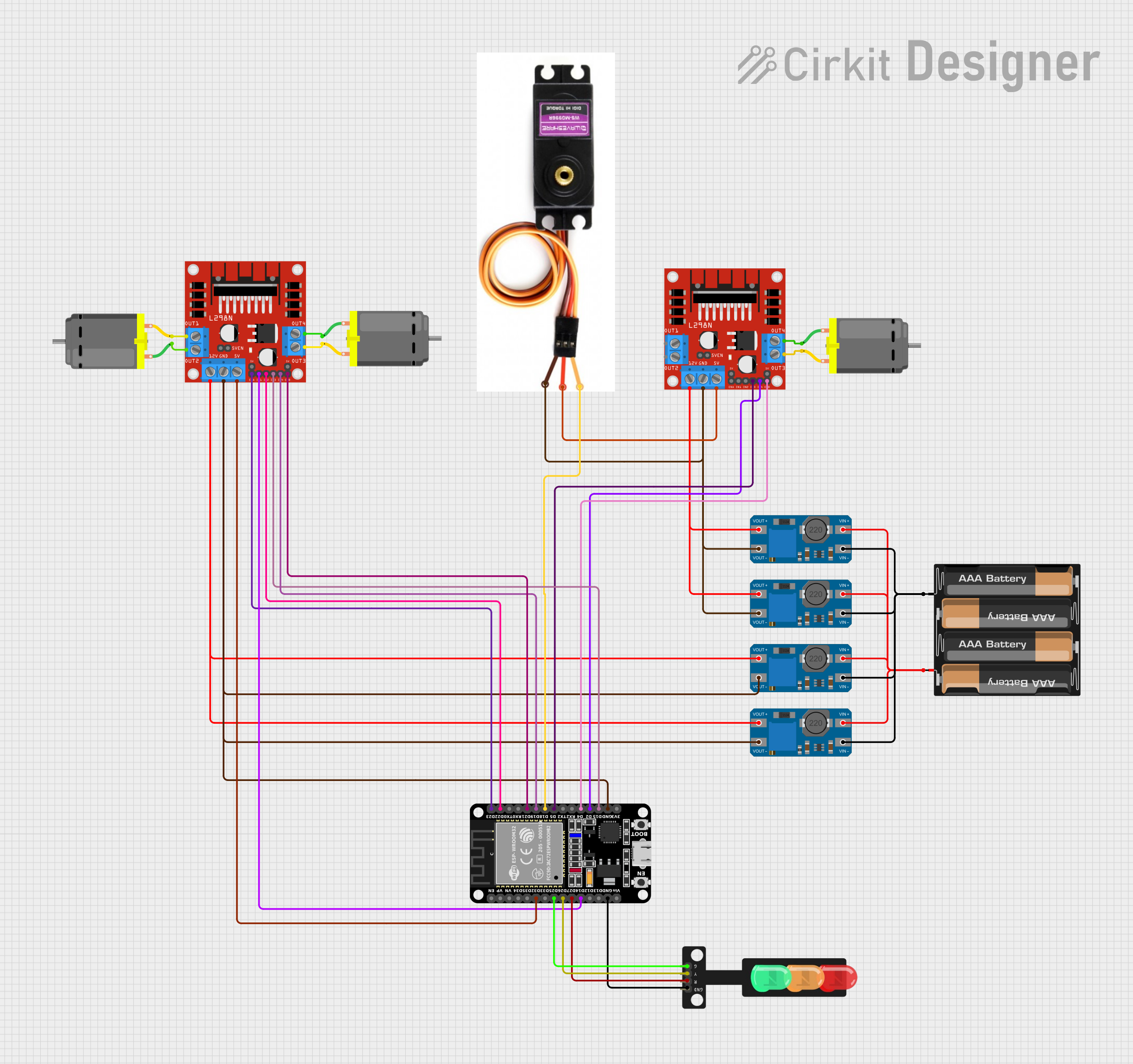
This circuit appears to be designed for controlling a set of traffic lights and driving multiple DC motors, possibly for a model intersection with moving parts. The ESP32 microcontroller is used as the central processing unit to control the traffic lights and the motors through the L298N motor drivers. The MT3608 modules are used to step up the voltage from the 4 x AAA battery mount to the required levels for the motor drivers and other components. The MG996R is a servo motor that is likely used for an additional movement mechanism within the system.
Component List
ESP32 (30 pin)
- Microcontroller with WiFi and Bluetooth capabilities.
- It has a variety of digital I/O pins for interfacing with other components.
MT3608
- A DC-DC step-up converter module.
- It boosts the voltage from the input supply to a higher level at the output.
L298N DC Motor Driver
- A dual H-bridge motor driver module.
- It allows for the control of two DC motors independently.
MG996R
- A high-torque digital servo motor.
- It is commonly used for steering mechanisms or other precise position control applications.
4 x AAA Battery Mount
- A battery holder for four AAA batteries.
- It provides the power source for the circuit.
DC Motor
- A standard DC motor used for rotational motion.
- It is driven by the L298N motor driver.
Traffic Light
- A simple traffic light module with Red, Yellow, and Green LEDs.
- It is controlled by the ESP32 to simulate traffic light changes.
Wiring Details
ESP32 (30 pin)
D32connected to L298N DC motor driver (5V)D25connected to Traffic Light (Green)D26connected to Traffic Light (Yellow)D27connected to Traffic Light (Red)D14,D23,D22,D21,D19,D18,D5,D4,D2,D15connected to various pins on L298N DC motor drivers and MG996R servo motor for control signalsGNDconnected to Traffic Light (GND), L298N DC motor driver (GND), and MG996R (GND)
MT3608
VOUT+andVOUT-connected to L298N DC motor drivers and MG996R for providing stepped-up voltageVIN+andVIN-connected to 4 x AAA Battery Mount for input voltage
L298N DC Motor Driver
5V,12V,ENA,ENB,IN1,IN2,IN3,IN4connected to ESP32 for motor controlOUT1,OUT2,OUT3,OUT4connected to DC Motors for driving the motorsGNDconnected to common ground
MG996R
Signal Lineconnected to ESP32 (D18) for control signalVccconnected to L298N DC motor driver (5V)GNDconnected to common ground
4 x AAA Battery Mount
+and-connected to MT3608 modules for power supply
DC Motor
pin 1andpin 2connected to L298N DC motor driver outputs
Traffic Light
Green,Yellow,Redconnected to ESP32 for control signalsGNDconnected to common ground
Documented Code
There is no code provided for the microcontrollers in the circuit. The code would typically include the initialization of the GPIO pins on the ESP32, the control logic for the traffic lights, and the PWM signals for the motor drivers and servo motor. Without the code, we cannot document the specific functionality or provide examples of how the ESP32 is programmed to interact with the other components in the circuit.