
ESP32 and L298N Motor Driver Bluetooth-Controlled Robotic Car
View and Edit Project In Cirkit Designer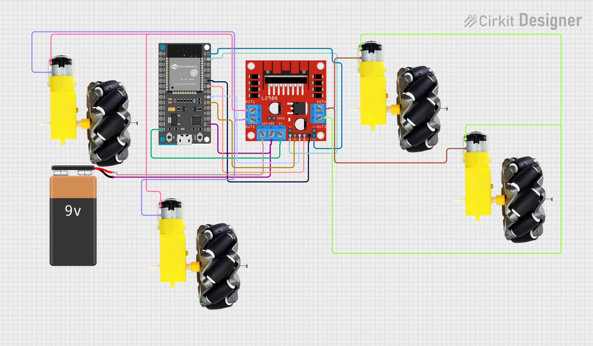
Circuit Documentation
Summary
This document provides a detailed overview of a circuit designed to control a set of motors using an ESP32 Devkit V1 microcontroller and an L298N DC motor driver. The circuit is powered by a 9V battery and includes four motor and wheel assemblies. The ESP32 is programmed to control the motors based on input from a Bluetooth gamepad.
Component List
ESP32 Devkit V1
- Description: A microcontroller with built-in Wi-Fi and Bluetooth capabilities.
- Pins: 3V3, GND, D15, D2, D4, RX2, TX2, D5, D18, D19, D21, RX0, TX0, D22, D23, EN, VP, VN, D34, D35, D32, D33, D25, D26, D27, D14, D12, D13, VIN
L298N DC Motor Driver
- Description: A dual H-Bridge motor driver that allows control of the speed and direction of two DC motors.
- Pins: OUT1, OUT2, 12V, GND, 5V, OUT3, OUT4, 5V-ENA-JMP-I, 5V-ENA-JMP-O, +5V-J1, +5V-J2, ENA, IN1, IN2, IN3, IN4, ENB
9V Battery
- Description: A power source for the circuit.
- Pins: -, +
Motor and Wheels (4 units)
- Description: DC motors with attached wheels.
- Pins: vcc, GND
Wiring Details
ESP32 Devkit V1
GND connected to:
- L298N DC Motor Driver (GND)
- 9V Battery (-)
RX2 connected to:
- L298N DC Motor Driver (IN1)
TX2 connected to:
- L298N DC Motor Driver (IN2)
D18 connected to:
- L298N DC Motor Driver (IN3)
D19 connected to:
- L298N DC Motor Driver (IN4)
D22 connected to:
- L298N DC Motor Driver (ENA)
D23 connected to:
- L298N DC Motor Driver (ENB)
VIN connected to:
- L298N DC Motor Driver (5V)
L298N DC Motor Driver
GND connected to:
- ESP32 Devkit V1 (GND)
- 9V Battery (-)
IN1 connected to:
- ESP32 Devkit V1 (RX2)
IN2 connected to:
- ESP32 Devkit V1 (TX2)
IN3 connected to:
- ESP32 Devkit V1 (D18)
IN4 connected to:
- ESP32 Devkit V1 (D19)
ENA connected to:
- ESP32 Devkit V1 (D22)
ENB connected to:
- ESP32 Devkit V1 (D23)
5V connected to:
- ESP32 Devkit V1 (VIN)
OUT1 connected to:
- Motor and Wheels (vcc)
- Motor and Wheels (vcc)
OUT2 connected to:
- Motor and Wheels (GND)
- Motor and Wheels (GND)
OUT3 connected to:
- Motor and Wheels (vcc)
- Motor and Wheels (vcc)
OUT4 connected to:
- Motor and Wheels (GND)
- Motor and Wheels (GND)
12V connected to:
- 9V Battery (+)
9V Battery
- connected to:
- ESP32 Devkit V1 (GND)
- L298N DC Motor Driver (GND)
+ connected to:
- L298N DC Motor Driver (12V)
Motor and Wheels
vcc connected to:
- L298N DC Motor Driver (OUT1)
- L298N DC Motor Driver (OUT3)
GND connected to:
- L298N DC Motor Driver (OUT2)
- L298N DC Motor Driver (OUT4)
Documented Code
Code File: sketch.ino
#include <DabbleESP32.h>

// Right motor
int enableRightMotor = 22;
int rightMotorPin1 = 4;
int rightMotorPin2 = 5;

// Left motor
int enableLeftMotor = 23;
int leftMotorPin1 = 18;
int leftMotorPin2 = 19;

const int MAX_MOTOR_SPEED = 255;

void setup() {
  pinMode(enableRightMotor, OUTPUT);
  pinMode(rightMotorPin1, OUTPUT);
  pinMode(rightMotorPin2, OUTPUT);
  pinMode(enableLeftMotor, OUTPUT);
  pinMode(leftMotorPin1, OUTPUT);
  pinMode(leftMotorPin2, OUTPUT);

  Dabble.begin("MyBluetoothCar");
}

void loop() {
  Dabble.processInput();

  int rightMotorSpeed = 0;
  int leftMotorSpeed = 0;

  if (GamePad.isUpPressed()) {
    rightMotorSpeed = MAX_MOTOR_SPEED;
    leftMotorSpeed = MAX_MOTOR_SPEED;
  }

  if (GamePad.isDownPressed()) {
    rightMotorSpeed = -MAX_MOTOR_SPEED;
    leftMotorSpeed = -MAX_MOTOR_SPEED;
  }

  if (GamePad.isLeftPressed()) {
    rightMotorSpeed = MAX_MOTOR_SPEED;
    leftMotorSpeed = -MAX_MOTOR_SPEED;
  }

  if (GamePad.isRightPressed()) {
    rightMotorSpeed = -MAX_MOTOR_SPEED;
    leftMotorSpeed = MAX_MOTOR_SPEED;
  }

  rotateMotor(rightMotorSpeed, leftMotorSpeed);
}

void rotateMotor(int rightMotorSpeed, int leftMotorSpeed) {
  // Control right motor
  if (rightMotorSpeed < 0) {
    digitalWrite(rightMotorPin1, LOW);
    digitalWrite(rightMotorPin2, HIGH);
  } else if (rightMotorSpeed > 0) {
    digitalWrite(rightMotorPin1, HIGH);
    digitalWrite(rightMotorPin2, LOW);
  } else {
    digitalWrite(rightMotorPin1, LOW);
    digitalWrite(rightMotorPin2, LOW);
  }

  // Control left motor
  if (leftMotorSpeed < 0) {
    digitalWrite(leftMotorPin1, LOW);
    digitalWrite(leftMotorPin2, HIGH);
  } else if (leftMotorSpeed > 0) {
    digitalWrite(leftMotorPin1, HIGH);
    digitalWrite(leftMotorPin2, LOW);
  } else {
    digitalWrite(leftMotorPin1, LOW);
    digitalWrite(leftMotorPin2, LOW);
  }
}
Code File: documentation.txt
#include <DabbleESP32.h>
#define CUSTOM_SETTINGS
#define INCLUDE_GAMEPAD_MODULE
#include <DabbleESP32.h>

//Right motor
int enableRightMotor=22;
int rightMotorPin1=4;
int rightMotorPin2=5;
//Left motor
int enableLeftMotor=23;
int leftMotorPin1=18;
int leftMotorPin2=19;

#define MAX_MOTOR_SPEED 255

const int PWMFreq = 1000; /* 1 KHz */
const int PWMResolution = 8;
const int rightMotorPWMSpeedChannel = 4;
const int leftMotorPWMSpeedChannel = 5;

void rotateMotor(int rightMotorSpeed, int leftMotorSpeed)
{
  if (rightMotorSpeed < 0)
  {
    digitalWrite(rightMotorPin1,LOW);
    digitalWrite(rightMotorPin2,HIGH);
  }
  else if (rightMotorSpeed > 0)
  {
    digitalWrite(rightMotorPin1,HIGH);
    digitalWrite(rightMotorPin2,LOW);
  }
  else
  {
    digitalWrite(rightMotorPin1,LOW);
    digitalWrite(rightMotorPin2,LOW);
  }

  if (leftMotorSpeed < 0)
  {
    digitalWrite(leftMotorPin1,LOW);
    digitalWrite(leftMotorPin2,HIGH);
  }
  else if (leftMotorSpeed > 0)
  {
    digitalWrite(leftMotorPin1,HIGH);
    digitalWrite(leftMotorPin2,LOW);
  }
  else
  {
    digitalWrite(leftMotorPin1,LOW);
    digitalWrite(leftMotorPin2,LOW);
  }

  ledcWrite(rightMotorPWMSpeedChannel, abs(rightMotorSpeed));
  ledcWrite(leftMotorPWMSpeedChannel, abs(leftMotorSpeed));
}

void setUpPinModes()
{
  pinMode(enableRightMotor,OUTPUT);
  pinMode(rightMotorPin1,OUTPUT);
  pinMode(rightMotorPin2,OUTPUT);

  pinMode(enableLeftMotor,OUTPUT);
  pinMode(leftMotorPin1,OUTPUT);
  pinMode(leftMotorPin2,OUTPUT);


  ledcSetup(rightMotorPWMSpeedChannel, PWMFreq, PWMResolution);
  ledcSetup(leftMotorPWMSpeedChannel, PWMFreq, PWMResolution);
  led