Arduino and ESP32-Based Smart Light and Motor Control System with DHT11 Sensor and I2C LCD
Circuit Documentation
Summary
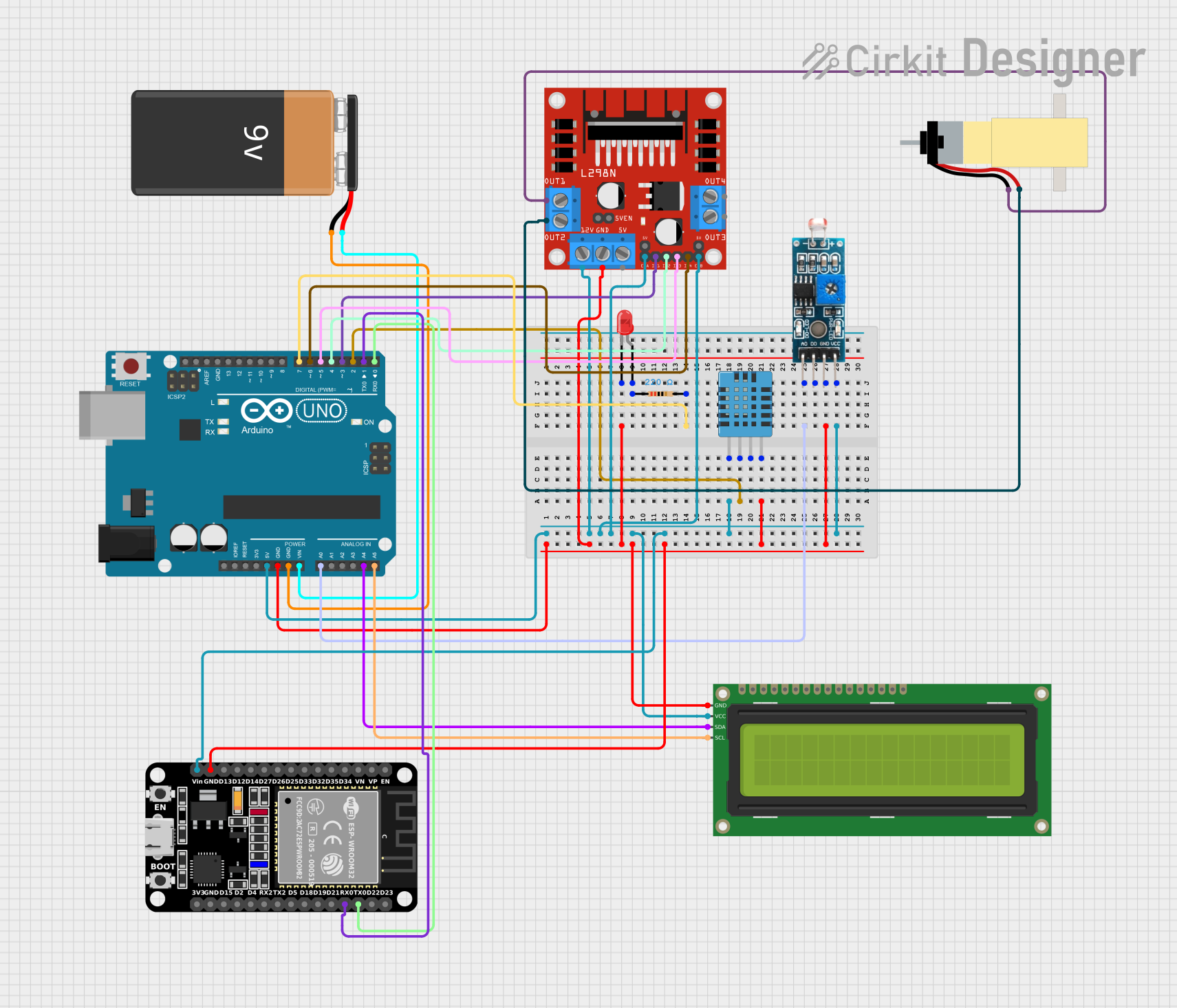
This circuit is designed to detect light using an LDR sensor. If no light is detected, it turns on an LED and rotates a motor clockwise. If light is detected, it turns off the LED and rotates the motor counter-clockwise. The system also detects temperature and humidity using a DHT11 sensor and displays this data on an LCD screen and an IoT system using ESP32. The motor can also be controlled via the IoT system, and temperature and humidity data can be viewed remotely.
Component List
Arduino UNO
- Description: Microcontroller board based on the ATmega328P.
- Pins: UNUSED, IOREF, Reset, 3.3V, 5V, GND, Vin, A0, A1, A2, A3, A4, A5, SCL, SDA, AREF, D13, D12, D11, D10, D9, D8, D7, D6, D5, D4, D3, D2, D1, D0
L298N DC Motor Driver
- Description: Dual H-Bridge motor driver.
- Pins: OUT1, OUT2, 12V, GND, 5V, OUT3, OUT4, 5V-ENA-JMP-I, 5V-ENA-JMP-O, +5V-J1, +5V-J2, ENA, IN1, IN2, IN3, IN4, ENB
DHT11 Humidity and Temperature Sensor
- Description: Digital sensor for measuring temperature and humidity.
- Pins: VDD, DATA, NULL, GND
Hobby Gearmotor with 48:1 Gearbox
- Description: Small DC motor with a 48:1 gearbox.
- Pins: pin 1, pin 2
9V Battery
- Description: Power source for the circuit.
- Pins: -, +
16x2 I2C LCD
- Description: LCD display with I2C interface.
- Pins: GND, VCC, SDA, SCL
LED: Two Pin (red)
- Description: Red LED.
- Pins: cathode, anode
Resistor
- Description: 220 Ohms resistor.
- Pins: pin1, pin2
- Properties: Resistance: 220 Ohms
ESP32 (30 pin)
- Description: Wi-Fi and Bluetooth microcontroller.
- Pins: EN, VP, VN, D34, D35, D32, D33, D25, D26, D27, D14, D12, D13, GND, Vin, D23, D22, TX0, RX0, D21, D19, D18, D5, TX2, RX2, D4, D2, D15, 3V3
Module LDR
- Description: Light-dependent resistor module.
- Pins: VCC, GND, DO, AO
Wiring Details
Arduino UNO
GND connected to:
- LED: Two Pin (red) cathode
- DHT11 Humidity and Temperature Sensor GND
- Module LDR GND
- L298N DC Motor Driver GND
- 16x2 I2C LCD GND
- ESP32 (30 pin) GND
- 9V Battery -
5V connected to:
- DHT11 Humidity and Temperature Sensor VDD
- Module LDR VCC
- L298N DC Motor Driver 12V
- L298N DC Motor Driver ENB
- L298N DC Motor Driver ENA
- 16x2 I2C LCD VCC
- ESP32 (30 pin) Vin
Vin connected to 9V Battery +
D2 connected to DHT11 Humidity and Temperature Sensor DATA
A0 connected to Module LDR AO
A4 connected to 16x2 I2C LCD SDA
A5 connected to 16x2 I2C LCD SCL
D7 connected to Resistor pin2
D6 connected to L298N DC Motor Driver IN4
D5 connected to L298N DC Motor Driver IN3
D4 connected to L298N DC Motor Driver IN2
D3 connected to L298N DC Motor Driver IN1
D1 connected to ESP32 (30 pin) RX0
D0 connected to ESP32 (30 pin) TX0
L298N DC Motor Driver
OUT1 connected to Hobby Gearmotor with 48:1 Gearbox pin 1
OUT2 connected to Hobby Gearmotor with 48:1 Gearbox pin 2
LED: Two Pin (red)
- anode connected to Resistor pin1
Resistor
- pin2 connected to Arduino UNO D7
Code Documentation
Arduino UNO Code
/*
 * This Arduino sketch is for a system that detects light using an LDR sensor.
 * If no light is detected, it turns on an LED and rotates a motor clockwise.
 * If light is detected, it turns off the LED and rotates the motor counter-
 * clockwise. The system also detects temperature and humidity using a DHT11
 * sensor and displays this data on an LCD screen and an IoT system using ESP32.
 * The motor can also be controlled via the IoT system, and temperature and
 * humidity data can be viewed remotely.
 */

#include <DHT.h>
#include <Wire.h>
#include <LiquidCrystal_I2C.h>

#define DHTPIN 2
#define DHTTYPE DHT11
#define LDRPIN A0
#define LEDPIN 7
#define IN1 3
#define IN2 4
#define IN3 5
#define IN4 6

DHT dht(DHTPIN, DHTTYPE);
LiquidCrystal_I2C lcd(0x27, 16, 2);

void setup() {
  pinMode(LEDPIN, OUTPUT);
  pinMode(IN1, OUTPUT);
  pinMode(IN2, OUTPUT);
  pinMode(IN3, OUTPUT);
  pinMode(IN4, OUTPUT);
  lcd.begin();
  lcd.backlight();
  dht.begin();
  Serial.begin(115200);
}

void loop() {
  int ldrValue = analogRead(LDRPIN);
  float h = dht.readHumidity();
  float t = dht.readTemperature();

  if (ldrValue < 500) {
    digitalWrite(LEDPIN, HIGH);
    rotateMotorClockwise();
  } else {
    digitalWrite(LEDPIN, LOW);
    rotateMotorCounterClockwise();
  }

  lcd.setCursor(0, 0);
  lcd.print("Temp: ");
  lcd.print(t);
  lcd.print(" C");
  lcd.setCursor(0, 1);
  lcd.print("Humidity: ");
  lcd.print(h);
  lcd.print(" %");

  sendToESP32(t, h);
  delay(2000);
}

void rotateMotorClockwise() {
  digitalWrite(IN1, HIGH);
  digitalWrite(IN2, LOW);
  digitalWrite(IN3, HIGH);
  digitalWrite(IN4, LOW);
}

void rotateMotorCounterClockwise() {
  digitalWrite(IN1, LOW);
  digitalWrite(IN2, HIGH);
  digitalWrite(IN3, LOW);
  digitalWrite(IN4, HIGH);
}

void sendToESP32(float temperature, float humidity) {
  Serial.print("Temp:");
  Serial.print(temperature);
  Serial.print(", Humidity:");
  Serial.println(humidity);
}
ESP32 Code
void setup() {
  // put your setup code here, to run once:
}

void loop() {
  // put your main code here, to run repeatedly:
}
This documentation provides a comprehensive overview of the circuit, including a summary, detailed component list, wiring details, and the code used in the microcontrollers.