
STM32F103C8T6-Based Environmental Monitoring System with Multi-Sensor Integration
View and Edit Project In Cirkit Designer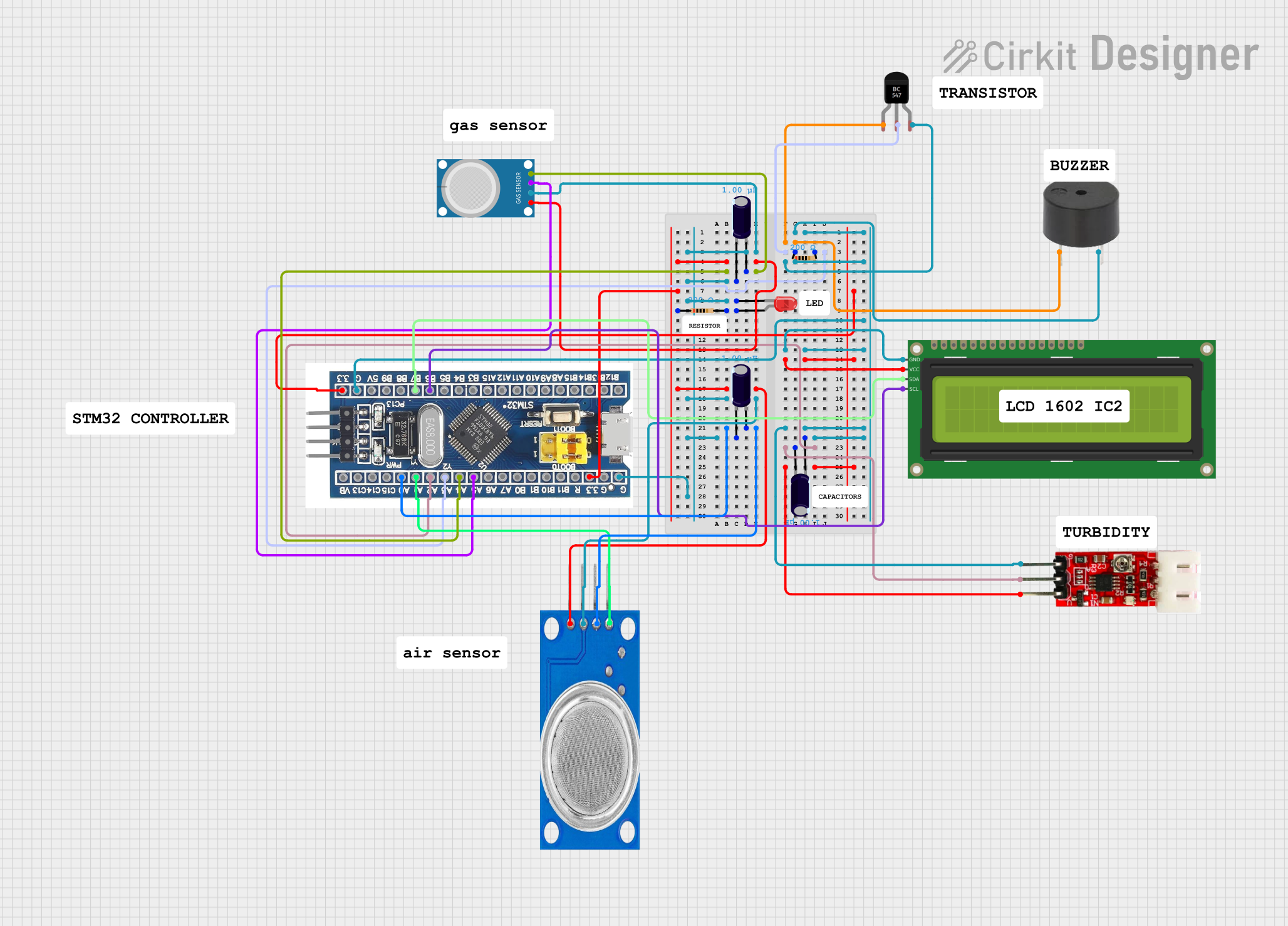
Circuit Documentation
Summary
This circuit is designed to interface various sensors and output devices with an STM32F103C8T6 microcontroller. The circuit includes sensors for gas detection (MQ135 and MQ-4), a turbidity module for water quality measurement, a buzzer for audible alerts, and a two-pin red LED for visual indication. The circuit also features a 16x2 I2C LCD for displaying information. The microcontroller manages sensor readings, controls the buzzer and LED, and updates the display. The circuit is powered by a 3.3V supply, and signal conditioning is provided by resistors and electrolytic capacitors.
Component List
- STM32F103C8T6 Microcontroller: A 32-bit microcontroller with various I/O pins for interfacing with peripherals.
- LED (Red, Two Pin): A simple red LED for visual indication.
- Resistor (200 Ohms): Two resistors used for current limiting and signal conditioning.
- MQ135 Gas Sensor: A sensor for detecting various hazardous gases.
- MQ-4 Gas Sensor: A sensor for detecting methane and natural gas.
- Turbidity Module: A sensor for measuring the turbidity of water, indicating its quality.
- Buzzer: An audible alert device.
- BC547 Transistor: A general-purpose NPN transistor used for switching the buzzer.
- 16x2 I2C LCD: A liquid crystal display with an I2C interface for showing information.
- Electrolytic Capacitor (1 µF): Three capacitors used for power supply decoupling and noise filtering.
Wiring Details
STM32F103C8T6 Microcontroller
- GND: Connected to the ground plane.
- 3.3V: Power supply to the MQ-4 and MQ135 gas sensors.
- A0: Connected to the MQ135 gas sensor's analog output and a 1 µF electrolytic capacitor.
- A1: Connected to the MQ135 gas sensor's digital output.
- A2: Connected to the turbidity module's output and a 1 µF electrolytic capacitor.
- A3: Connected to the base of the BC547 transistor through a 200 Ohm resistor.
- A4: Connected to the MQ-4 gas sensor's analog output and a 1 µF electrolytic capacitor.
- A5: Connected to the MQ-4 gas sensor's digital output.
- B6: Connected to the SCL pin of the 16x2 I2C LCD.
- B7: Connected to the SDA pin of the 16x2 I2C LCD.
LED (Red, Two Pin)
- Cathode: Connected to the ground plane.
- Anode: Connected to a 200 Ohm resistor.
Resistor (200 Ohms)
- Two resistors are used in the circuit. One is connected between the anode of the LED and the microcontroller. The other is connected between the base of the BC547 transistor and the microcontroller.
MQ135 Gas Sensor
- VCC: Connected to the 3.3V power supply.
- GND: Connected to the ground plane.
- A0: Connected to the A0 pin of the microcontroller and a 1 µF electrolytic capacitor.
- D0: Connected to the A1 pin of the microcontroller.
MQ-4 Gas Sensor
- VCC: Connected to the 3.3V power supply.
- GND: Connected to the ground plane.
- A0: Connected to the A4 pin of the microcontroller and a 1 µF electrolytic capacitor.
- D0: Connected to the A5 pin of the microcontroller.
Turbidity Module
- VCC: Connected to the 3.3V power supply.
- GND: Connected to the ground plane.
- OUT: Connected to the A2 pin of the microcontroller and a 1 µF electrolytic capacitor.
Buzzer
- PIN: Connected to the collector of the BC547 transistor.
- GND: Connected to the ground plane.
BC547 Transistor
- Collector: Connected to the buzzer.
- Base: Connected to the A3 pin of the microcontroller through a 200 Ohm resistor.
- Emitter: Connected to the ground plane.
16x2 I2C LCD
- GND: Connected to the ground plane.
- VCC: Connected to the 3.3V power supply.
- SDA: Connected to the B7 pin of the microcontroller.
- SCL: Connected to the B6 pin of the microcontroller.
Electrolytic Capacitor (1 µF)
- Three capacitors are used for decoupling and noise filtering. They are connected between the analog pins of the sensors (A0, A2, A4) and the ground plane.
Documented Code
No code was provided for the microcontroller. The documentation of the code would typically include descriptions of the functions, initialization routines, main loop, interrupt service routines, and any libraries used for interfacing with the peripherals. Since no code is available, this section cannot be completed.