
Arduino-Based Depth and Environmental Monitor with LCD Display and Buzzer Alert
View and Edit Project In Cirkit Designer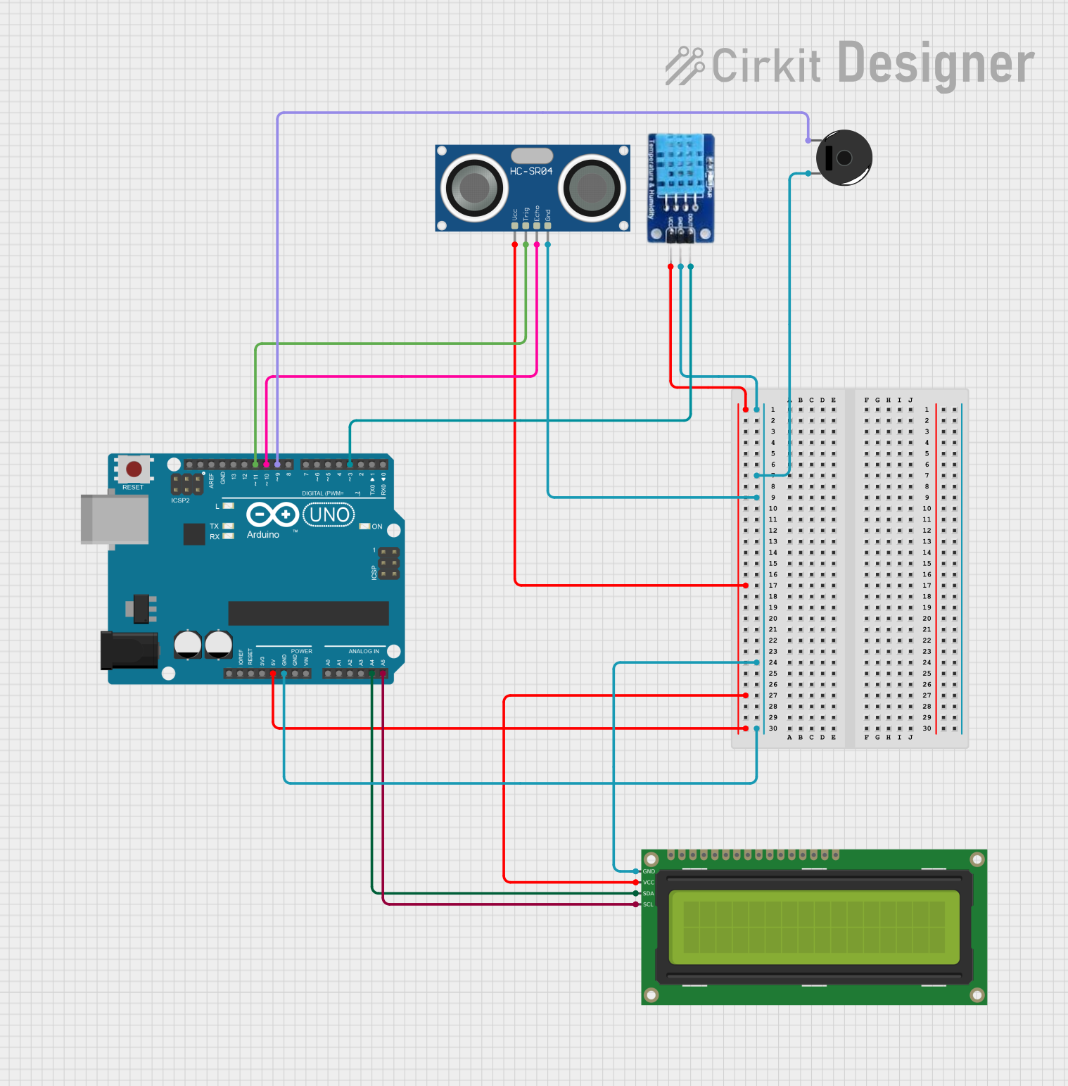
Circuit Documentation
Summary
This circuit is designed to measure depth, humidity, and temperature using an HC-SR04 ultrasonic sensor and a DHT11 sensor. If the measured depth is less than 5 cm, a piezo buzzer will ring. All measurements are displayed on a 16x2 I2C LCD. The circuit is controlled by an Arduino UNO microcontroller.
Component List
DHT11
- Description: Humidity and Temperature Sensor
- Pins: DATA, GND, VCC
16x2 I2C LCD
- Description: LCD Display with I2C Interface
- Pins: GND, VCC, SDA, SCL
Piezo Buzzer
- Description: Sound Buzzer
- Pins: pin 1, pin 2
HC-SR04 Ultrasonic Sensor
- Description: Ultrasonic Distance Sensor
- Pins: VCC, TRIG, ECHO, GND
Arduino UNO
- Description: Microcontroller Board
- Pins: UNUSED, IOREF, Reset, 3.3V, 5V, GND, Vin, A0, A1, A2, A3, A4, A5, SCL, SDA, AREF, D13, D12, D11, D10, D9, D8, D7, D6, D5, D4, D3, D2, D1, D0
Wiring Details
DHT11
- VCC: Connected to Arduino UNO 5V
- GND: Connected to Arduino UNO GND
- DATA: Connected to Arduino UNO D3
16x2 I2C LCD
- GND: Connected to Arduino UNO GND
- VCC: Connected to Arduino UNO 5V
- SDA: Connected to Arduino UNO A4
- SCL: Connected to Arduino UNO A5
Piezo Buzzer
- pin 1: Connected to Arduino UNO D9
- pin 2: Connected to Arduino UNO GND
HC-SR04 Ultrasonic Sensor
- VCC: Connected to Arduino UNO 5V
- GND: Connected to Arduino UNO GND
- TRIG: Connected to Arduino UNO D11
- ECHO: Connected to Arduino UNO D10
Arduino UNO
- 5V: Supplies power to DHT11, HC-SR04, and 16x2 I2C LCD
- GND: Common ground for all components
- A4: I2C SDA line for 16x2 I2C LCD
- A5: I2C SCL line for 16x2 I2C LCD
- D3: Data line for DHT11
- D9: Control line for Piezo Buzzer
- D11: Trigger line for HC-SR04
- D10: Echo line for HC-SR04
Code Documentation
/*
 * This Arduino sketch measures depth, humidity, and temperature using an
 * HC-SR04 ultrasonic sensor and a DHT11 sensor. If the measured depth is
 * less than 5 cm, a piezo buzzer will ring. All measurements are displayed
 * on a 16x2 I2C LCD.
 */

#include <Wire.h>
#include <LiquidCrystal_I2C.h>
#include <DHT.h>

// Pin definitions
#define TRIG_PIN 11
#define ECHO_PIN 10
#define DHT_PIN 3
#define BUZZER_PIN 9

// Constants
#define DHT_TYPE DHT11
#define DEPTH_THRESHOLD 5.0

// Initialize sensors and LCD
DHT dht(DHT_PIN, DHT_TYPE);
LiquidCrystal_I2C lcd(0x27, 16, 2);

void setup() {
  // Initialize serial communication
  Serial.begin(9600);
  // Initialize sensors and LCD
  dht.begin();
  lcd.begin();
  lcd.backlight();
  // Initialize pin modes
  pinMode(TRIG_PIN, OUTPUT);
  pinMode(ECHO_PIN, INPUT);
  pinMode(BUZZER_PIN, OUTPUT);
}

void loop() {
  // Measure depth
  float depth = measureDepth();
  // Measure humidity and temperature
  float humidity = dht.readHumidity();
  float temperature = dht.readTemperature();
  // Display measurements on LCD
  lcd.setCursor(0, 0);
  lcd.print("Depth: ");
  lcd.print(depth);
  lcd.print(" cm");
  lcd.setCursor(0, 1);
  lcd.print("Temp: ");
  lcd.print(temperature);
  lcd.print(" C Hum: ");
  lcd.print(humidity);
  lcd.print(" %");
  // Check depth and ring buzzer if necessary
  if (depth < DEPTH_THRESHOLD) {
    digitalWrite(BUZZER_PIN, HIGH);
  } else {
    digitalWrite(BUZZER_PIN, LOW);
  }
  // Wait before next measurement
  delay(2000);
}

float measureDepth() {
  // Send trigger pulse
  digitalWrite(TRIG_PIN, LOW);
  delayMicroseconds(2);
  digitalWrite(TRIG_PIN, HIGH);
  delayMicroseconds(10);
  digitalWrite(TRIG_PIN, LOW);
  // Measure echo pulse duration
  long duration = pulseIn(ECHO_PIN, HIGH);
  // Calculate depth in cm
  float depth = duration * 0.034 / 2;
  return depth;
}
This code initializes the sensors and LCD, measures depth, humidity, and temperature, and displays the measurements on the LCD. If the depth is less than 5 cm, the piezo buzzer will ring. The measurements are updated every 2 seconds.