Cirkit Designer
Your all-in-one circuit design IDE
Home /
Project Documentation
Arduino Nano and NRF24L01 Battery-Powered Wireless Microphone with LED Indicator
Circuit Documentation
Summary
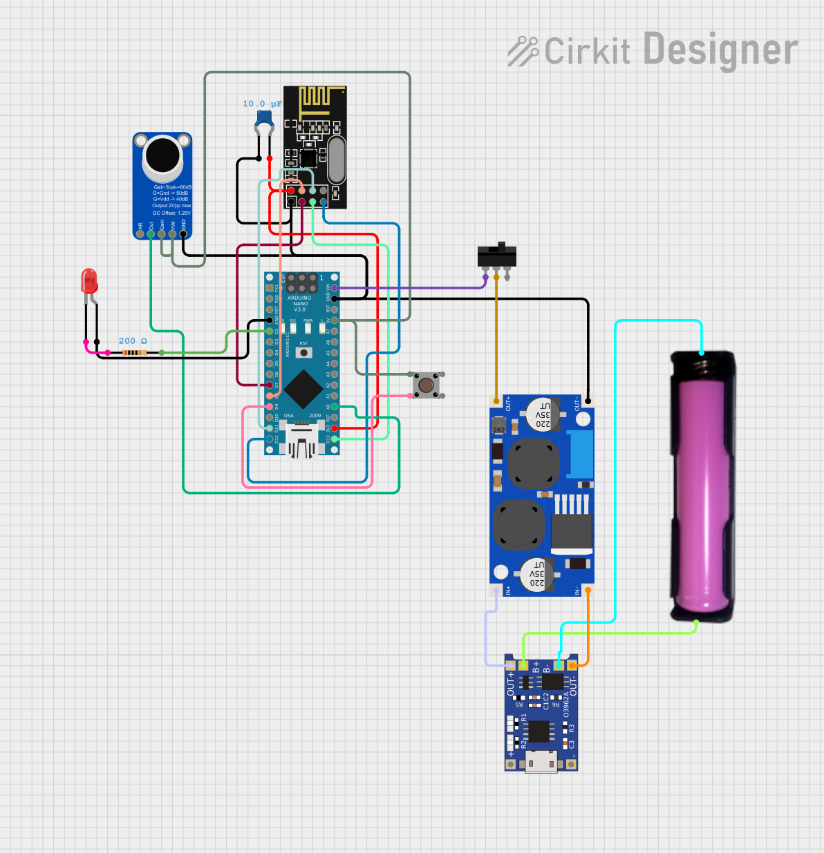
This document provides a detailed overview of a circuit that includes an Arduino Nano, an NRF24L01 wireless module, an Adafruit MAX9814 Electret Microphone Amplifier, a pushbutton, a red LED, a resistor, a ceramic capacitor, a 18650 battery in a holder, a TP4056 battery charger, an XL6009E1 boost converter, and a toggle switch. The circuit is designed to interface various components with the Arduino Nano for control and communication purposes.
Component List
Resistor
- Description: A resistor with a resistance of 200 Ohms.
- Pins: pin1, pin2
Arduino Nano
- Description: A microcontroller board based on the ATmega328P.
- Pins: D1/TX, D0/RX, RESET, GND, D2, D3, D4, D5, D6, D7, D8, D9, D10, D11/MOSI, D12/MISO, VIN, 5V, A7, A6, A5, A4, A3, A2, A1, A0, AREF, 3V3, D13/SCK
NRF24L01
- Description: A wireless transceiver module.
- Pins: IRQ (not used), MOSI, CSN, VCC (3V), GND, CE, SCK, MISO
Adafruit MAX9814 Electret Microphone Amplifier
- Description: An amplifier for electret microphones.
- Pins: GND, VDD, GAIN, OUTPUT, A/R
LED: Two Pin (red)
- Description: A red LED.
- Pins: cathode, anode
Pushbutton
- Description: A pushbutton switch.
- Pins: Pin 3 (out), Pin 4 (out), Pin 1 (in), Pin 2 (in)
Ceramic Capacitor
- Description: A ceramic capacitor with a capacitance of 0.00001 Farads.
- Pins: pin0, pin1
18650 in holder
- Description: A 18650 battery in a holder.
- Pins: GND, VCC
TP4056
- Description: A lithium battery charger module.
- Pins: OUT-, B-, B+, OUT+, IN-, IN+
XL6009E1 Boost Converter
- Description: A boost converter module.
- Pins: IN+, IN-, OUT-, OUT+
Toggle Switch
- Description: A toggle switch.
- Pins: L1, COM, L2
Wiring Details
Resistor
- pin1 is connected to the cathode of the LED: Two Pin (red).
- pin2 is connected to D2 of the Arduino Nano.
Arduino Nano
- GND is connected to the anode of the LED: Two Pin (red).
- D2 is connected to pin2 of the Resistor.
- D7 is connected to CE of the NRF24L01.
- D8 is connected to CSN of the NRF24L01.
- D9 is connected to Pin 4 (out) of the Pushbutton.
- D11/MOSI is connected to MOSI of the NRF24L01.
- D12/MISO is connected to MISO of the NRF24L01.
- VIN is connected to L1 of the Toggle Switch.
- GND is connected to GND of the NRF24L01, GND of the Adafruit MAX9814 Electret Microphone Amplifier, OUT- of the XL6009E1 Boost Converter, and pin0 of the Ceramic Capacitor.
- 5V is connected to VDD and GAIN of the Adafruit MAX9814 Electret Microphone Amplifier, and Pin 2 (in) of the Pushbutton.
- A0 is connected to OUTPUT of the Adafruit MAX9814 Electret Microphone Amplifier.
- 3V3 is connected to VCC (3V) of the NRF24L01 and pin1 of the Ceramic Capacitor.
- D13/SCK is connected to SCK of the NRF24L01.
NRF24L01
- CE is connected to D7 of the Arduino Nano.
- CSN is connected to D8 of the Arduino Nano.
- MOSI is connected to D11/MOSI of the Arduino Nano.
- MISO is connected to D12/MISO of the Arduino Nano.
- GND is connected to GND of the Arduino Nano, GND of the Adafruit MAX9814 Electret Microphone Amplifier, OUT- of the XL6009E1 Boost Converter, and pin0 of the Ceramic Capacitor.
- VCC (3V) is connected to 3V3 of the Arduino Nano and pin1 of the Ceramic Capacitor.
- SCK is connected to D13/SCK of the Arduino Nano.
Adafruit MAX9814 Electret Microphone Amplifier
- GND is connected to GND of the Arduino Nano, GND of the NRF24L01, OUT- of the XL6009E1 Boost Converter, and pin0 of the Ceramic Capacitor.
- VDD is connected to 5V of the Arduino Nano.
- GAIN is connected to 5V of the Arduino Nano.
- OUTPUT is connected to A0 of the Arduino Nano.
LED: Two Pin (red)
- cathode is connected to pin1 of the Resistor.
- anode is connected to GND of the Arduino Nano.
Pushbutton
- Pin 4 (out) is connected to D9 of the Arduino Nano.
- Pin 2 (in) is connected to 5V of the Arduino Nano.
Ceramic Capacitor
- pin0 is connected to GND of the Arduino Nano, GND of the NRF24L01, GND of the Adafruit MAX9814 Electret Microphone Amplifier, and OUT- of the XL6009E1 Boost Converter.
- pin1 is connected to 3V3 of the Arduino Nano and VCC (3V) of the NRF24L01.
18650 in holder
- GND is connected to B- of the TP4056.
- VCC is connected to B+ of the TP4056.
TP4056
- B- is connected to GND of the 18650 in holder.
- B+ is connected to VCC of the 18650 in holder.
- OUT- is connected to IN- of the XL6009E1 Boost Converter.
- OUT+ is connected to IN+ of the XL6009E1 Boost Converter.
XL6009E1 Boost Converter
- IN- is connected to OUT- of the TP4056.
- IN+ is connected to OUT+ of the TP4056.
- OUT- is connected to GND of the Arduino Nano, GND of the NRF24L01, GND of the Adafruit MAX9814 Electret Microphone Amplifier, and pin0 of the Ceramic Capacitor.
- OUT+ is connected to COM of the Toggle Switch.
Toggle Switch
- L1 is connected to VIN of the Arduino Nano.
- COM is connected to OUT+ of the XL6009E1 Boost Converter.
Documented Code
Arduino Nano Code (sketch.ino)
void setup() {
  // put your setup code here, to run once:

}

void loop() {
  // put your main code here, to run repeatedly:

}
Additional Documentation (documentation.txt)
This document provides a comprehensive overview of the circuit, including a detailed component list, wiring details, and the code used for the Arduino Nano.