
Arduino Mega ADK Controlled Robotic Vehicle with Ultrasonic Sensors and IR Remote
View and Edit Project In Cirkit Designer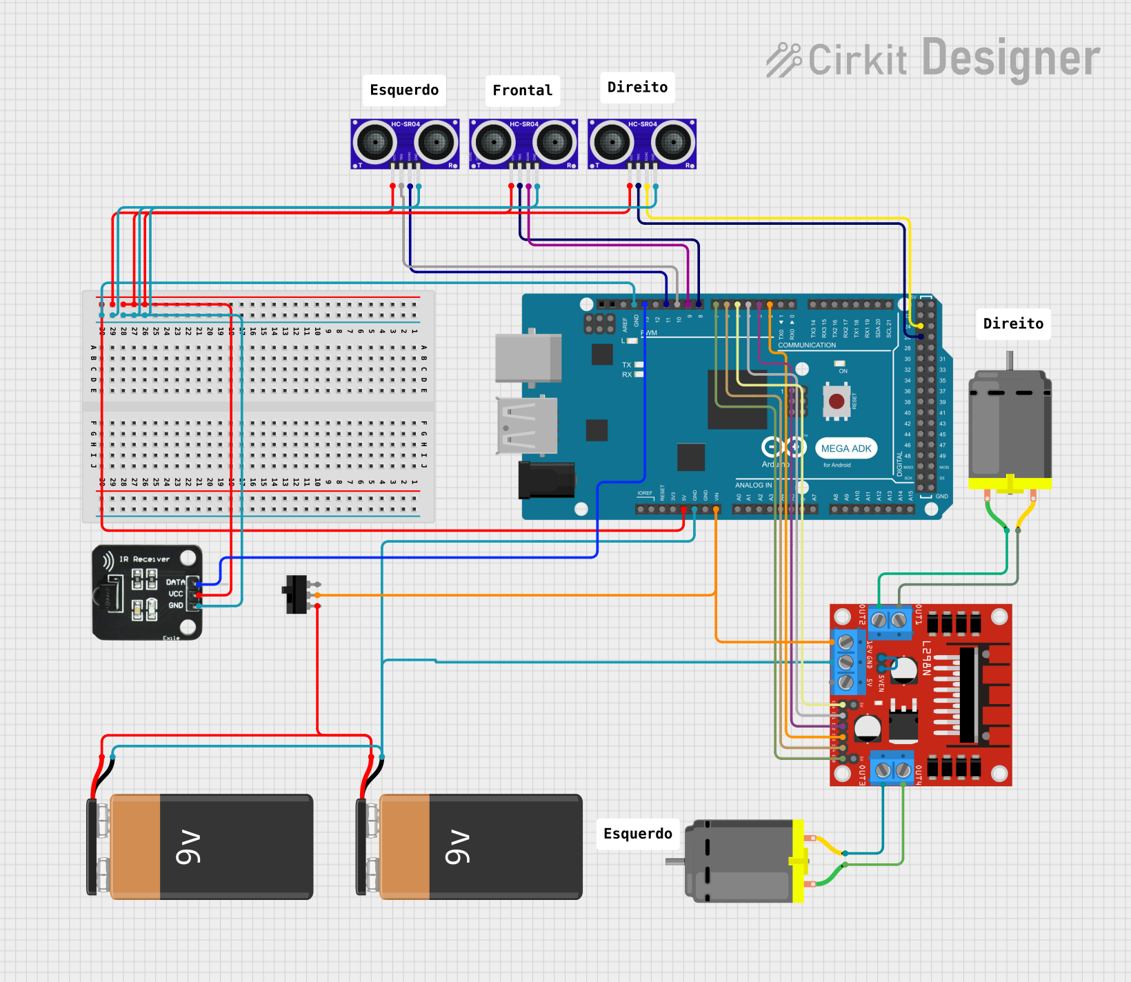
Circuit Documentation
Summary
The circuit in question appears to be a control system utilizing an Arduino Mega ADK (Rev3) as the central processing unit. It interfaces with multiple HC-SR04 ultrasonic sensors, an IR receiver, a L298N DC motor driver, and two DC motors. The system is powered by two 9V batteries, and a toggle switch is used to control the power flow to the Arduino and the motor driver. The HC-SR04 sensors are likely used for distance measurement, while the IR receiver may be used for remote control purposes. The L298N motor driver controls the two DC motors, which could be part of a robotic vehicle or a similar application.
Component List
Arduino Mega ADK (Rev3)
- Microcontroller board based on the ATmega2560
- It has 54 digital input/output pins (of which 15 can be used as PWM outputs), 16 analog inputs, 4 UARTs (hardware serial ports), a 16 MHz crystal oscillator, a USB connection, a power jack, an ICSP header, and a reset button.
HC-SR04 Ultrasonic Sensor
- Ultrasonic distance sensor
- Provides 2cm to 400cm non-contact measurement functionality with a ranging accuracy that can reach up to 3mm.
IR Receiver
- Infrared receiver for remote control systems
- Typically used to receive signals from IR remotes and decode them for further action.
L298N DC Motor Driver
- Dual H-Bridge motor driver
- Can drive two DC motors or one bipolar stepper motor.
9V Battery
- Standard 9V battery used for power supply.
Toggle Switch
- A simple switch to control the connection of the circuit to the power source.
DC Motor
- A standard DC motor used for motion-related applications.
Wiring Details
Arduino Mega ADK (Rev3)
- GND: Connected to the ground pins of all HC-SR04 sensors, IR Receiver, and L298N motor driver.
- 5V: Powers all HC-SR04 sensors and the IR Receiver.
- VIN: Connected to the 12V input of the L298N motor driver through a toggle switch.
- Digital Pins (D2-D13 PWM): Control signals for the HC-SR04 sensors, IR Receiver, and L298N motor driver.
HC-SR04 Ultrasonic Sensor
- VCC: Powered by the 5V output from the Arduino.
- TRIG: Trigger pin connected to a digital pin on the Arduino.
- ECHO: Echo pin connected to a digital pin on the Arduino.
- GND: Ground connection shared with the Arduino.
IR Receiver
- DATA: Connected to a digital pin on the Arduino.
- VCC: Powered by the 5V output from the Arduino.
- GND: Ground connection shared with the Arduino.
L298N DC Motor Driver
- 12V: Powered by the VIN pin of the Arduino through a toggle switch.
- GND: Ground connection shared with the Arduino.
- 5V: Output used to power the logic circuit of the motor driver.
- ENA, ENB: Enable pins connected to digital pins on the Arduino for motor speed control.
- IN1-IN4: Input pins connected to digital pins on the Arduino for motor direction control.
- OUT1-OUT4: Output pins connected to the DC motors.
9V Battery
- +: Connected to the common terminal of the toggle switch.
- -: Ground connection shared with the Arduino and motor driver.
Toggle Switch
- COM: Connected to the VIN pin of the Arduino.
- L1: Connected to the positive terminal of the 9V batteries.
DC Motor
- pin 1 and pin 2: Connected to the output pins of the L298N motor driver.
Documented Code
There is no code provided for the microcontroller. For a functional circuit, embedded code would be required to initialize and control the pins connected to the HC-SR04 sensors, IR receiver, and L298N motor driver. The code would include setup routines, control algorithms, and possibly communication protocols if remote control functionality is implemented.