
Arduino Mega and UNO-Based Biometric Access System with NFC and SD Card Logging
View and Edit Project In Cirkit Designer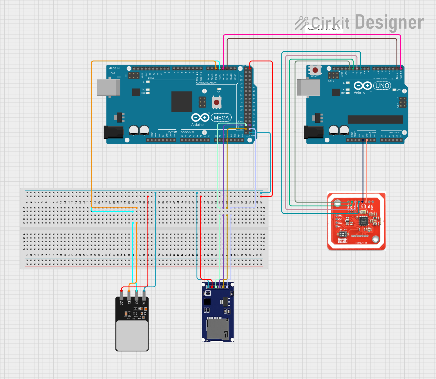
Circuit Documentation
Summary
This circuit involves an Arduino Mega 2560 and an Arduino UNO microcontroller, interfacing with an NFC/RFID reader (PN532), an SD module, and a fingerprint scanner. The Arduino Mega 2560 is primarily responsible for reading analog values from various sensors, while the Arduino UNO handles communication with the NFC/RFID reader. The SD module is used for data storage, and the fingerprint scanner is used for biometric identification.
Component List
Arduino Mega 2560
- Description: A microcontroller board based on the ATmega2560.
- Pins: IOREF, RESET, 3V3, 5V, GND, VIN, A0-A15, D21/SCL, D20/SDA, D19/RX1, D18/TX1, D17 PWM/RX2, D16 PWM/TX2, D15/RX3, D14/TX3, D0 RX0, D1 TX0, D2-D13 PWM, AREF, SDA, SCL, D22-D53.
Arduino UNO
- Description: A microcontroller board based on the ATmega328P.
- Pins: UNUSED, IOREF, Reset, 3.3V, 5V, GND, Vin, A0-A5, SCL, SDA, AREF, D0-D13.
NFC/RFID reader PN532
- Description: A module for reading NFC/RFID tags.
- Pins: GND, VCC, SDA, SCL, SCK, MISO, MOSI, SS, IRQ, RSTO.
SD Module
- Description: A module for interfacing with SD cards.
- Pins: CS, SCK, MOSI, MISO, VCC, GND.
Fingerprint Scanner
- Description: A module for fingerprint recognition.
- Pins: VCC, TX, RX, GND.
Wiring Details
Arduino Mega 2560
- D17 PWM/RX2 connected to Fingerprint Scanner RX
- D16 PWM/TX2 connected to Fingerprint Scanner TX
- D50 connected to SD Module MISO
- D51 connected to SD Module MOSI
- D52 connected to SD Module SCK
- D53 connected to SD Module CS
- 5V connected to Fingerprint Scanner VCC, SD Module VCC
- GND connected to Fingerprint Scanner GND, SD Module GND
- D19/RX1 connected to Arduino UNO D1
- D18/TX1 connected to Arduino UNO D0
Arduino UNO
- D1 connected to Arduino Mega 2560 D19/RX1
- D0 connected to Arduino Mega 2560 D18/TX1
- 5V connected to NFC/RFID reader PN532 VCC
- GND connected to NFC/RFID reader PN532 GND
- D13 connected to NFC/RFID reader PN532 SCK
- D12 connected to NFC/RFID reader PN532 MISO
- D11 connected to NFC/RFID reader PN532 MOSI
- D10 connected to NFC/RFID reader PN532 SS
NFC/RFID reader PN532
- VCC connected to Arduino UNO 5V
- GND connected to Arduino UNO GND
- SCK connected to Arduino UNO D13
- MISO connected to Arduino UNO D12
- MOSI connected to Arduino UNO D11
- SS connected to Arduino UNO D10
SD Module
- MISO connected to Arduino Mega 2560 D50
- MOSI connected to Arduino Mega 2560 D51
- SCK connected to Arduino Mega 2560 D52
- CS connected to Arduino Mega 2560 D53
- VCC connected to Arduino Mega 2560 5V
- GND connected to Arduino Mega 2560 GND
Fingerprint Scanner
- RX connected to Arduino Mega 2560 D17 PWM/RX2
- TX connected to Arduino Mega 2560 D16 PWM/TX2
- VCC connected to Arduino Mega 2560 5V
- GND connected to Arduino Mega 2560 GND
Documented Code
Arduino Mega 2560 Code
#include <Wire.h>
#include <Adafruit_ADS1X15.h>

// Create an ADS1115 object
Adafruit_ADS1115 ads;  // Use default constructor

void setup() {
  Serial.begin(9600);

  // Initialize the ADS1115 module
  if (!ads.begin(0x48)) {  // Pass the I2C address here
    Serial.println("Failed to initialize ADS1115.");
    while (1);
  }

  Serial.println("ADS1115 initialized.");
}

void loop() {
  // Read analog values from the MQ sensors
  int16_t adc0 = ads.readADC_SingleEnded(0);  // MQ-2 on A0
  int16_t adc1 = ads.readADC_SingleEnded(1);  // MQ-3 on A1
  int16_t adc2 = ads.readADC_SingleEnded(2);  // MQ-7 on A2
  int16_t adc3 = ads.readADC_SingleEnded(3);  // MQ-135 on A3

  // Convert ADC values to voltage (optional, for reference)
  float voltage0 = adc0 * 0.1875 / 1000;  // ADS1115 16-bit, ±6.144V range, 0.1875mV per bit
  float voltage1 = voltage0;  // Same for other channels
  float voltage2 = voltage0;
  float voltage3 = voltage0;

  // Print ADC values and voltage to the Serial Monitor
  Serial.print("MQ-2 (A0) ADC: "); Serial.print(adc0);
  Serial.print(", Voltage: "); Serial.print(voltage0); Serial.println(" V");

  Serial.print("MQ-3 (A1) ADC: "); Serial.print(adc1);
  Serial.print(", Voltage: "); Serial.print(voltage1); Serial.println(" V");

  Serial.print("MQ-7 (A2) ADC: "); Serial.print(adc2);
  Serial.print(", Voltage: "); Serial.print(voltage2); Serial.println(" V");

  Serial.print("MQ-135 (A3) ADC: "); Serial.print(adc3);
  Serial.print(", Voltage: "); Serial.print(voltage3); Serial.println(" V");

  // Add delay for readability
  delay(1000);
}
Arduino UNO Code
void setup() {
  // put your setup code here, to run once:

}

void loop() {
  // put your main code here, to run repeatedly:

}
This documentation provides a comprehensive overview of the circuit, including a summary, detailed component list, wiring details, and documented code for the microcontrollers.