
Arduino Micro Pro-based Input Control Interface with Rotary Encoder and Joystick
View and Edit Project In Cirkit Designer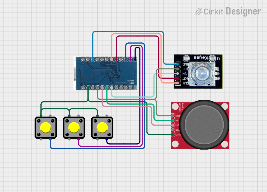
Circuit Documentation
Summary
This circuit integrates an Arduino Micro Pro with a rotary encoder, an analog joystick, and three pushbuttons. The Arduino Micro Pro serves as the central processing unit, interfacing with the input devices to receive user inputs. The rotary encoder provides rotational input, the analog joystick allows for two-dimensional control, and the pushbuttons serve as simple binary input devices. The circuit is designed to capture a variety of user interactions, making it suitable for applications such as gaming controllers or interactive projects.
Component List
Arduino Micro Pro
- Description: A microcontroller board based on the ATmega32U4.
- Pins: RAW, RST, VCC, A3, A2, A1, A0, 15, 14, 16, 10, 9, 8, 7, 6, 5, 4, 3, 2, GND, RX, TX
Rotary Encoder
- Description: An input device that provides rotational position feedback.
- Pins: clk, dt, sw, gnd, +
Pushbutton (x3)
- Description: A simple switch mechanism for controlling a circuit.
- Pins: Pin 2, Pin 1, Pin 3, Pin 4
Analog Joystick (Wokwi Compatible)
- Description: A two-axis joystick with a pushbutton feature.
- Pins: VCC, VERT, HORZ, SEL, GND
Wiring Details
Arduino Micro Pro
- VCC connected to Rotary Encoder (+) and Analog Joystick (VCC)
- A3 connected to Analog Joystick (HORZ)
- A2 connected to Analog Joystick (VERT)
- A1 connected to Rotary Encoder (sw)
- Pin 9 connected to Pushbutton 3 (Pin 3)
- Pin 8 connected to Pushbutton 2 (Pin 3)
- Pin 7 connected to Pushbutton 1 (Pin 3)
- Pin 5 connected to Rotary Encoder (dt)
- Pin 4 connected to Rotary Encoder (clk)
- GND connected to Rotary Encoder (gnd), all Pushbuttons (Pin 1), and Analog Joystick (GND)
Rotary Encoder
- (+) connected to Arduino Micro Pro (VCC)
- clk connected to Arduino Micro Pro (Pin 4)
- dt connected to Arduino Micro Pro (Pin 5)
- sw connected to Arduino Micro Pro (A1)
- gnd connected to Arduino Micro Pro (GND)
Pushbutton 1
- Pin 3 connected to Arduino Micro Pro (Pin 7)
- Pin 1 connected to Arduino Micro Pro (GND)
Pushbutton 2
- Pin 3 connected to Arduino Micro Pro (Pin 8)
- Pin 1 connected to Arduino Micro Pro (GND)
Pushbutton 3
- Pin 3 connected to Arduino Micro Pro (Pin 9)
- Pin 1 connected to Arduino Micro Pro (GND)
Analog Joystick (Wokwi Compatible)
- VCC connected to Arduino Micro Pro (VCC)
- VERT connected to Arduino Micro Pro (A2)
- HORZ connected to Arduino Micro Pro (A3)
- SEL not connected
- GND connected to Arduino Micro Pro (GND)
Documented Code
No code has been provided for the microcontrollers in the circuit. The functionality of the circuit will depend on the embedded code that is written to interpret the signals from the rotary encoder, the analog joystick, and the pushbuttons. The code should initialize the input pins, read the inputs in the main loop, and perform actions based on the inputs received.