
Circuit Documentation
Summary
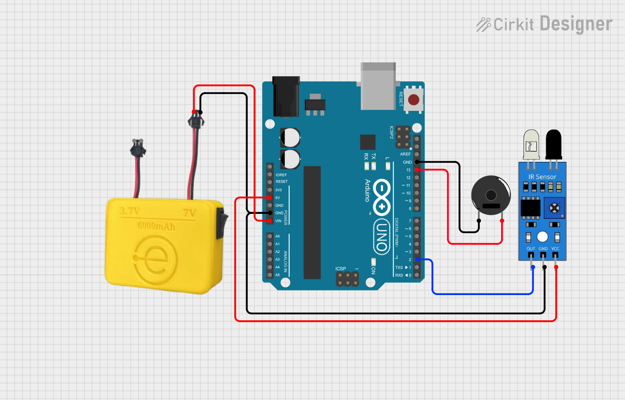
This circuit consists of an Arduino UNO microcontroller, an IR sensor, a Piezo Buzzer, and a power supply module (MAHIR 7.0). The IR sensor detects objects and sends a signal to the Arduino, which then activates the Piezo Buzzer. The power supply module provides the necessary voltage and ground connections to the circuit.
Component List
Arduino UNO
- Description: A microcontroller board based on the ATmega328P.
- Pins: UNUSED, IOREF, Reset, 3.3V, 5V, GND, Vin, A0, A1, A2, A3, A4, A5, SCL, SDA, AREF, D13, D12, D11, D10, D9, D8, D7, D6, D5, D4, D3, D2, D1, D0
IR Sensor
- Description: An infrared sensor used to detect objects.
- Pins: out, gnd, vcc
Piezo Buzzer
- Description: A simple buzzer that produces sound when activated.
- Pins: pin 1, pin 2
MAHIR 7.0
- Description: A power supply module providing 7V and 3.7V outputs.
- Pins: GND, 7V, 3.7v
Wiring Details
Arduino UNO
- 5V connected to vcc of the IR Sensor
- GND connected to GND of the MAHIR 7.0
- GND connected to gnd of the IR Sensor
- Vin connected to 7V of the MAHIR 7.0
- GND connected to pin 1 of the Piezo Buzzer
- D13 connected to pin 2 of the Piezo Buzzer
- D2 connected to out of the IR Sensor
IR Sensor
- vcc connected to 5V of the Arduino UNO
- gnd connected to GND of the Arduino UNO
- out connected to D2 of the Arduino UNO
Piezo Buzzer
- pin 1 connected to GND of the Arduino UNO
- pin 2 connected to D13 of the Arduino UNO
MAHIR 7.0
- GND connected to GND of the Arduino UNO
- 7V connected to Vin of the Arduino UNO
Code Documentation
Arduino UNO Code
void setup() {
  // put your setup code here, to run once:

}

void loop() {
  // put your main code here, to run repeatedly:

}
This code is a basic template for the Arduino UNO. The setup() function is where you initialize your settings, and the loop() function is where the main code runs repeatedly. In this circuit, you would typically add code to read the IR sensor's output and activate the Piezo Buzzer accordingly.