Arduino UNO Controlled Linear Actuators and Stepper Motor with LED Feedback
Circuit Documentation
Summary
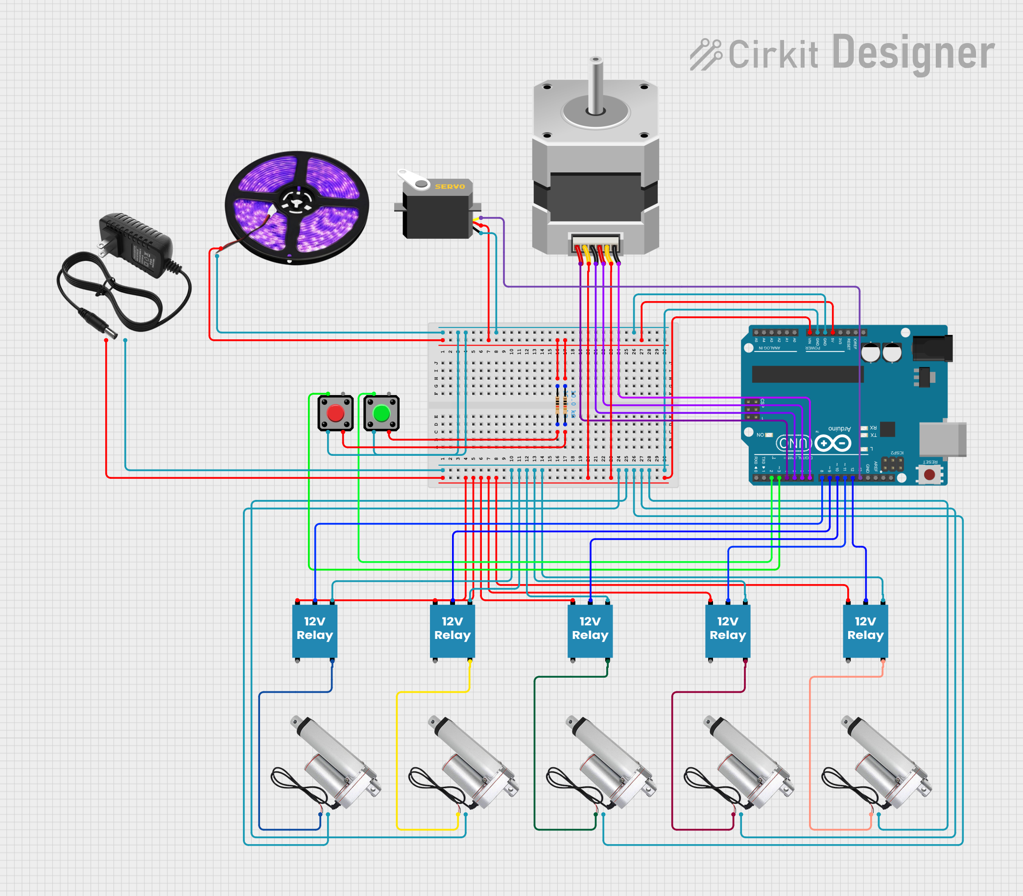
This circuit is designed to control a series of linear actuators and a stepper motor using an Arduino UNO microcontroller. The circuit includes pushbuttons for user input, resistors for input pull-up configurations, relays for controlling the actuators, a stepper motor, a servo motor, and LED light strips for indication or aesthetic purposes. The power supply for the circuit is a 12V source, which powers the relays, actuators, and the stepper motor, while the Arduino UNO is powered through its Vin pin. The servo and LED light strips are powered by the Arduino's 5V output.
Component List
- Arduino UNO: A microcontroller board based on the ATmega328P, with a variety of digital and analog I/O pins.
- Linear Actuator: An electromechanical device used for motion control, typically to move something in a linear path.
- 12V Relay: An electrically operated switch that allows the control of a high-power circuit with a low-power signal.
- 12V Power Supply: Provides the necessary power for the components that require 12V, such as the relays and actuators.
- Pushbutton: A simple switch mechanism for controlling some aspect of a machine or a process.
- Resistor: An electrical component that limits or regulates the flow of electrical current in an electronic circuit.
- Stepper Motor (Unipolar): A type of DC electric motor that divides a full rotation into a number of equal steps.
- Servo: A rotary actuator or linear actuator that allows for precise control of angular or linear position.
- LED Light Strips (Violet): Strips of LEDs used for lighting, often with an adhesive backing for easy installation.
Wiring Details
Arduino UNO
- 5V: Connected to the VCC of the LED light strips, VCC of the servo, and pin 1 of two 10k Ohm resistors.
- GND: Common ground for the LED light strips, servo, pushbuttons, and the 12V power supply.
- Vin: Connected to the positive terminal of the 12V power supply.
- D2-D13: Digital pins connected to pushbuttons and control pins of the relays and stepper motor.
Linear Actuators
- +: Connected to the Normally Open (NO) contacts of their respective relays.
- -: Common ground with the Arduino UNO and 12V power supply.
12V Relay
- +: Connected to the positive terminal of the 12V power supply.
- -: Common ground with the Arduino UNO and 12V power supply.
- C (Coil): Connected to various digital pins on the Arduino UNO for control.
- NO (Normally Open): Connected to the positive pin of the respective linear actuators.
12V Power Supply
- +: Provides power to the relays, stepper motor, and the Arduino UNO's Vin pin.
- -: Common ground with the Arduino UNO and all other components requiring ground.
Pushbuttons
- Pin 1: Connected to digital pins D2 and D3 on the Arduino UNO.
- Pin 2: Common ground with the Arduino UNO.
- Pin 3: Connected to pin 2 of the respective 10k Ohm resistors.
Resistors
- pin1: Connected to the 5V output on the Arduino UNO and to pin 3 of the respective pushbuttons.
- pin2: Connected to pin 3 of the respective pushbuttons.
Stepper Motor (Unipolar)
- A, B, C, D: Connected to digital pins D4, D6, D5, D7 on the Arduino UNO respectively.
- COMMON_1, COMMON_2: Connected to the positive terminal of the 12V power supply.
Servo
- gnd: Common ground with the Arduino UNO.
- vcc: Connected to the 5V output on the Arduino UNO.
- pulse: Connected to digital pin D13 on the Arduino UNO.
LED Light Strips (Violet)
- VCC: Connected to the 5V output on the Arduino UNO.
- GND: Common ground with the Arduino UNO.
Documented Code
void setup() {
  // put your setup code here, to run once:

}

void loop() {
  // put your main code here, to run repeatedly:

}
The provided code is a template for the Arduino UNO with empty setup and loop functions. The setup function is intended to initialize the pins and set the initial state of the circuit. The loop function will contain the main logic that should be executed repeatedly, such as reading inputs from the pushbuttons, controlling the relays, and driving the stepper motor and servo.