
Arduino Mega 2560-Based Motor Control System with Optical Encoder and Current/Voltage Sensing
View and Edit Project In Cirkit Designer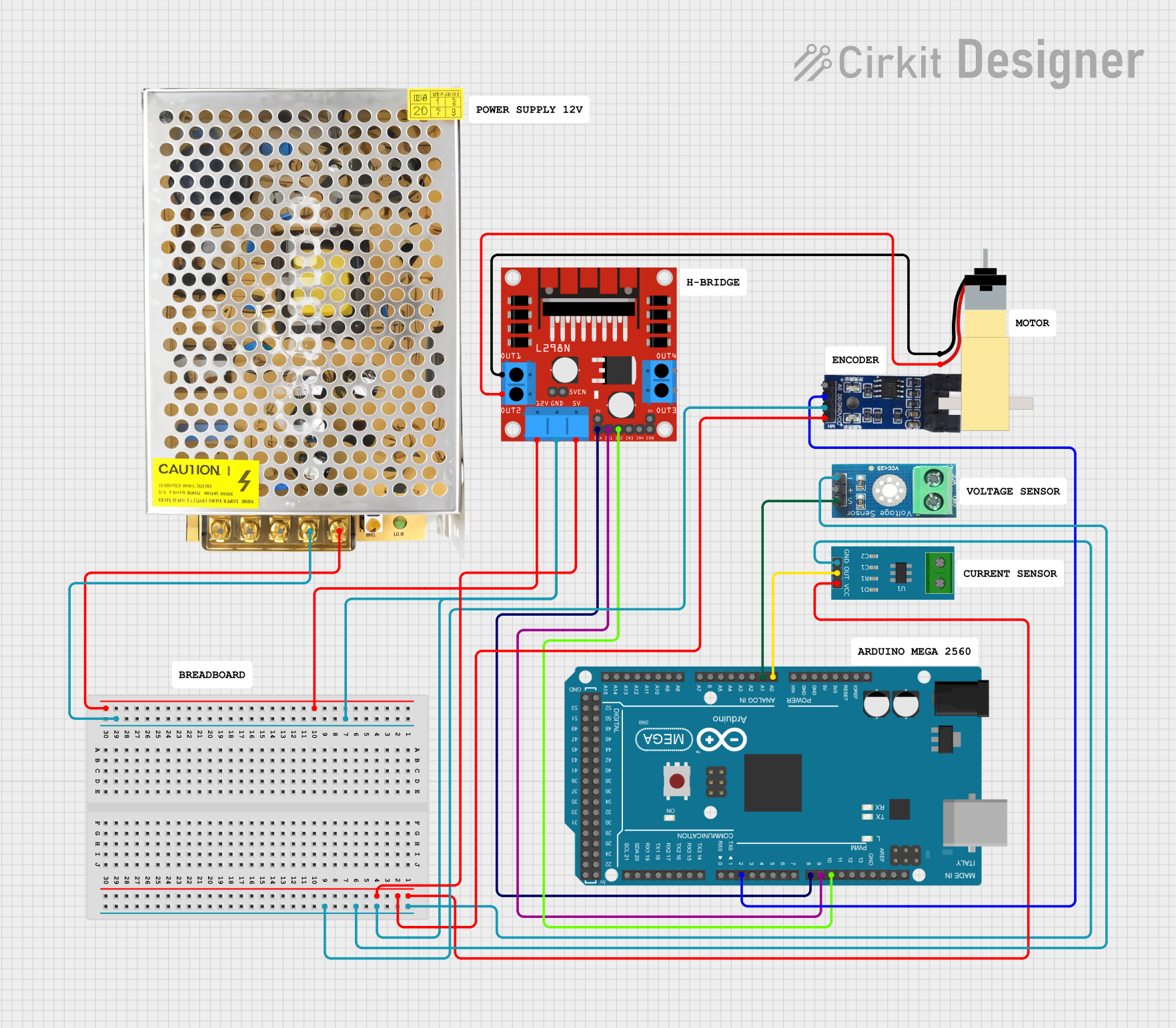
Circuit Documentation
Summary
This document provides a detailed overview of a circuit that includes various sensors, a motor driver, a gear motor, and an Arduino Mega 2560 microcontroller. The circuit is designed to control a motor and read sensor data, which is processed by the Arduino. The components are interconnected to achieve the desired functionality.
Component List
Puente H carrito
- Description: Motor driver for controlling the gear motor.
- Pins: OUT1, OUT2, OUT3, OUT4, 12V, GND, 5V, ENA, IN1, IN2, IN3, IN4, ENB, 5VEN
Optical Encoder Sensor Module
- Description: Sensor module for measuring rotational position.
- Pins: A0, D0, GND, VCC
Voltage Sensor DC 25V
- Description: Sensor for measuring voltage up to 25V.
- Pins: +, -, output, gnd, vcc
Hobby Gearmotor with 48:1 gearbox
- Description: Gear motor with a 48:1 reduction ratio.
- Pins: pin 1, pin 2
Arduino Mega 2560
- Description: Microcontroller for processing sensor data and controlling the motor driver.
- Pins: IOREF, RESET, 3V3, 5V, GND, VIN, A0, A1, A2, A3, A4, A5, A6, A7, A8, A9, A10, A11, A12, A13, A14, A15, D21/SCL, D20/SDA, D19/RX1, D18/TX1, D17 PWM/RX2, D16 PWM/TX2, D15/RX3, D14/TX3, D0 RX0, D1 TX0, D2 PWM, D3 PWM, D4 PWM, D5 PWM, D6 PWM, D7 PWM, D8 PWM, D9 PWM, D10 PWM, D11 PWM, D12 PWM, D13 PWM, AREF, SDA, SCL, D52, D50, D48, D46, D44, D42, D40, D38, D36, D34, D32, D30, D28, D26, D24, D22, D53, D51, D49, D47, D45, D43, D41, D39, D37, D35, D33, D31, D29, D27, D25, D23
SMPS
- Description: Switched-mode power supply for providing power to the circuit.
- Pins: L, N, GND, -DC, +DC
Current Sensor 5A
- Description: Sensor for measuring current up to 5A.
- Pins: 1, 2, GND, OUT, VCC
Wiring Details
Puente H carrito
- 5V is connected to VCC of the Optical Encoder Sensor Module and VCC of the Current Sensor 5A.
- GND is connected to GND of the Optical Encoder Sensor Module, - of the Voltage Sensor DC 25V, GND of the Current Sensor 5A, and -DC of the SMPS.
- 12V is connected to +DC of the SMPS.
- OUT1 is connected to pin 1 of the Hobby Gearmotor with 48:1 gearbox.
- OUT2 is connected to pin 2 of the Hobby Gearmotor with 48:1 gearbox.
- ENA is connected to D8 PWM of the Arduino Mega 2560.
- IN1 is connected to D9 PWM of the Arduino Mega 2560.
- IN2 is connected to D10 PWM of the Arduino Mega 2560.
Optical Encoder Sensor Module
- VCC is connected to 5V of the Puente H carrito.
- GND is connected to GND of the Puente H carrito.
- D0 is connected to D2 PWM of the Arduino Mega 2560.
Voltage Sensor DC 25V
- - is connected to GND of the Puente H carrito.
- output is connected to A1 of the Arduino Mega 2560.
Hobby Gearmotor with 48:1 gearbox
- pin 1 is connected to OUT1 of the Puente H carrito.
- pin 2 is connected to OUT2 of the Puente H carrito.
Arduino Mega 2560
- D8 PWM is connected to ENA of the Puente H carrito.
- D9 PWM is connected to IN1 of the Puente H carrito.
- D10 PWM is connected to IN2 of the Puente H carrito.
- A0 is connected to OUT of the Current Sensor 5A.
- D2 PWM is connected to D0 of the Optical Encoder Sensor Module.
- A1 is connected to output of the Voltage Sensor DC 25V.
SMPS
- +DC is connected to 12V of the Puente H carrito.
- -DC is connected to GND of the Puente H carrito.
Current Sensor 5A
- VCC is connected to 5V of the Puente H carrito.
- GND is connected to GND of the Puente H carrito.
- OUT is connected to A0 of the Arduino Mega 2560.
Documented Code
Arduino Mega 2560 Code
void setup() {
  // put your setup code here, to run once:

}

void loop() {
  // put your main code here, to run repeatedly:

}
This code is a basic template for the Arduino Mega 2560. The setup function is used to initialize any settings or configurations, and the loop function contains the main code that runs repeatedly. You can add your specific logic for controlling the motor and reading sensor data within these functions.