
ESP32-Controlled Smart Home Automation System with I2C LCD Feedback
View and Edit Project In Cirkit Designer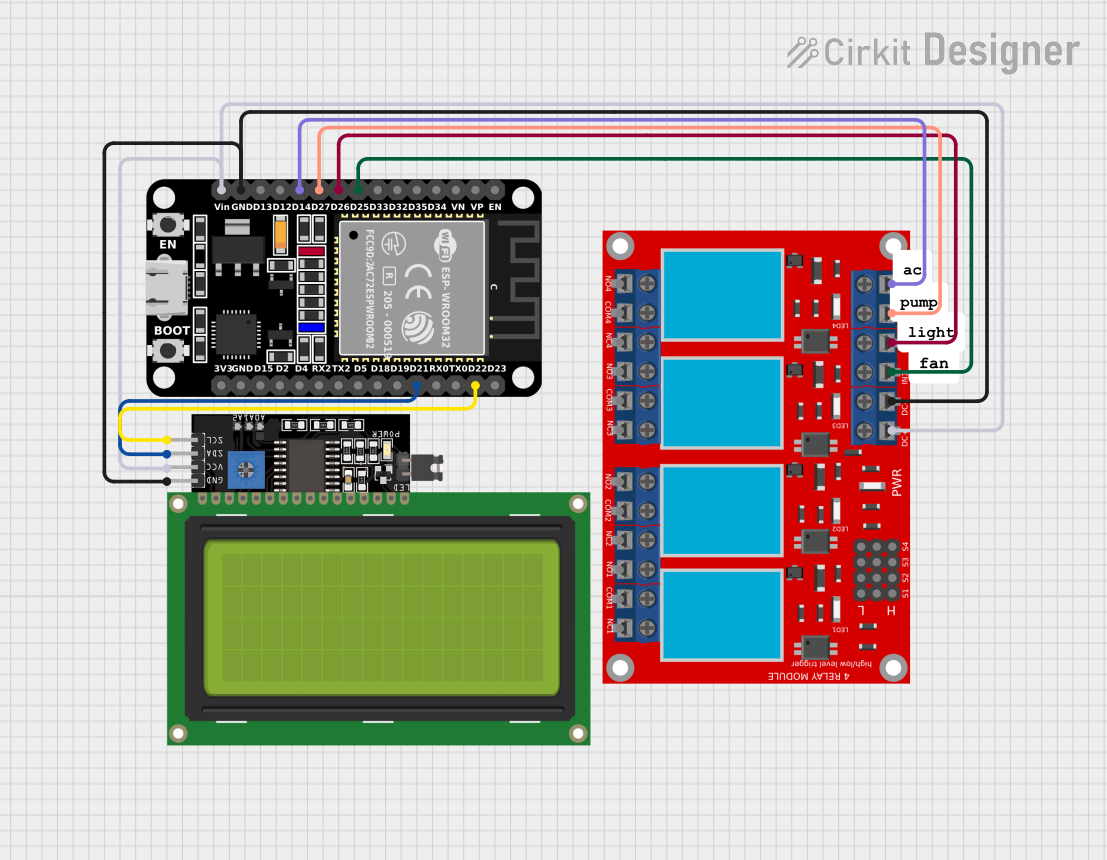
Circuit Documentation
Summary
The circuit in question is designed to control a 4-channel relay module using an ESP32 microcontroller. The ESP32 is also interfaced with a 20x4 LCD display over I2C for user feedback. The relay module can control various loads, which are not specified in the provided information. The ESP32 is programmed to connect to a Wi-Fi network and interface with the Blynk IoT platform, allowing remote control of the connected loads via virtual pins. The LCD display shows the status of each load controlled by the relay module.
Component List
ESP32 (30 pin)
- Description: A microcontroller with Wi-Fi capabilities, featuring a variety of digital and analog pins.
- Purpose: Acts as the central processing unit of the circuit, controlling the relay module and the LCD display, as well as handling Wi-Fi connectivity.
LCD Display 20x4 I2C
- Description: An alphanumeric liquid crystal display with an I2C interface, capable of displaying 4 lines of 20 characters each.
- Purpose: Provides a user interface to display the status of the loads controlled by the relay module.
4 Channel Relay Module
- Description: A module with 4 electromechanical relays capable of controlling high power loads.
- Purpose: Allows the ESP32 to control up to four separate loads, such as lights, fans, or pumps.
Wiring Details
ESP32 (30 pin)
- D25: Connected to Relay Module IN 1
- D26: Connected to Relay Module IN 2
- D27: Connected to Relay Module IN 3
- D14: Connected to Relay Module IN 4
- D22: Connected to LCD Display SCL
- D21: Connected to LCD Display SDA
- GND: Common ground with Relay Module and LCD Display
- Vin: Connected to Relay Module VCC+ and LCD Display VCC
LCD Display 20x4 I2C
- SCL: Connected to ESP32 D22
- SDA: Connected to ESP32 D21
- VCC: Connected to ESP32 Vin
- GND: Common ground with ESP32 and Relay Module
4 Channel Relay Module
- IN 1: Connected to ESP32 D25
- IN 2: Connected to ESP32 D26
- IN 3: Connected to ESP32 D27
- IN 4: Connected to ESP32 D14
- VCC+: Connected to ESP32 Vin
- VCC- (GND): Common ground with ESP32 and LCD Display
Documented Code
#define BLYNK_TEMPLATE_ID "TMPL3eoClDWHt"
#define BLYNK_TEMPLATE_NAME "project"
#define BLYNK_AUTH_TOKEN "p3gTohJHQL_1TlT8Z16XCBZkD07SGxWN"
#include <LiquidCrystal_I2C.h>
#include <Wire.h>
#include <WiFi.h>
#include <WiFiClient.h>
#include <BlynkSimpleEsp32.h>

LiquidCrystal_I2C lcd(0x27, 20, 4);

char ssid[] =  "wifiname";
char pass[] =  "password";

const int fan = 25;
const int light = 26;
const int pump = 27;
const int ac = 14;
const int baudRate = 115200;
const int interval = 100;

BLYNK_CONNECTED() {
  // Request the latest state from the server
  Blynk.syncVirtual(V0);
  Blynk.syncVirtual(V1);
  Blynk.syncVirtual(V2);
  Blynk.syncVirtual(V3);
}

void setup()
{
  lcd.init();
  lcd.backlight();
  lcd.setCursor(1, 0);
  lcd.print("WELCOME");
  Serial.begin(baudRate);

  Blynk.begin(BLYNK_AUTH_TOKEN, ssid, pass);

  pinMode(fan, OUTPUT);
  pinMode(light, OUTPUT);
  pinMode(pump, OUTPUT);
  pinMode(ac, OUTPUT);
  lcd.clear();
  delay(1000);
}

void loop()
{
  Blynk.run();
  mydisplay(digitalRead(fan), digitalRead(light), digitalRead(pump), digitalRead(ac));
}

BLYNK_WRITE(V0) {
  int pinValue = param.asInt();
  digitalWrite(fan, pinValue);
}

BLYNK_WRITE(V1) {
  int pinValue = param.asInt();
  digitalWrite(light, pinValue);
}

BLYNK_WRITE(V2) {
  int pinValue = param.asInt();
  digitalWrite(pump, pinValue);
}

BLYNK_WRITE(V3) {
  int pinValue = param.asInt();
  digitalWrite(ac, pinValue);
}

void mydisplay(int f, int l, int p, int a) {
  lcd.setCursor(0,0);
  lcd.print("Fan L1  Pump  L2");
  lcd.setCursor(0,1);

  if(f == 0)
    lcd.print("OFF");
  else
    lcd.print("ON ");

  if(l == 0)
    lcd.print(" OFF");
  else
    lcd.print(" ON ");

  if(p == 0)
    lcd.print(" OFF ");
  else
    lcd.print(" ON ");

  if(a == 0)
    lcd.print("  OFF");
  else
    lcd.print("  ON ");
  delay(1000);
  lcd.clear();
}
This code initializes the LCD and sets up the ESP32 to connect to the specified Wi-Fi network and Blynk server. It configures the relay control pins as outputs and handles Blynk virtual pin writes to control the state of the relays. The mydisplay function updates the LCD with the status of each relay.