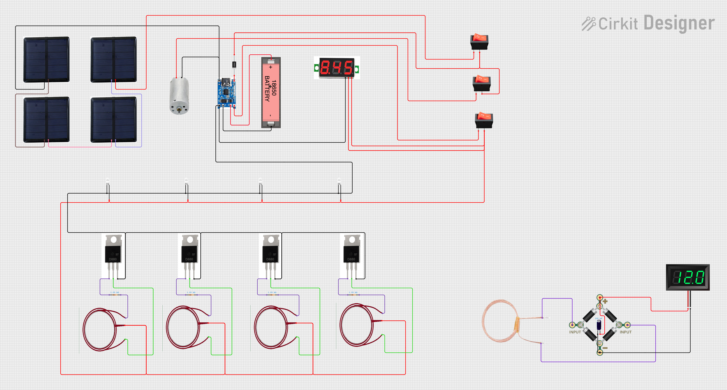
Solar-Powered Battery Charging and Monitoring System with TP4056 and 7-Segment Voltmeter

Circuit Documentation
Summary
This document provides a detailed overview of a circuit designed with various components including a TP4056 Battery Charging Protection Module, Li-ion 18650 Battery, LEDs, transistors, resistors, and more. The circuit is designed to manage power distribution, charging, and display voltage levels using a combination of solar cells, a DC generator, and a battery. The circuit also includes multiple switches for controlling the flow of electricity.
Component List
TP4056 Battery Charging Protection Module (Type C)
- Pins: OUT +, B+, B-, OUT -, +, -
- Description: Manages battery charging and protection.
1N4007 Rectifier Diode
- Pins: Cathode, Anode
- Description: Used for rectification in the circuit.
Rocker Switch
- Pins: output, input
- Description: Used to control the flow of electricity.
Li-ion 18650 Battery
- Pins: +, -
- Description: Provides power to the circuit.
LED: Two Pin (white)
- Pins: cathode, anode
- Description: Used for visual indication.
Copper Coil 30 Turns
- Pins: Pin 1, + PIN, Pin 3
- Description: Used for inductance in the circuit.
Transistor
- Pins: 1 BASE, 2 COLLECTOR, 3 EMITTER
- Description: Used for switching and amplification.
Solar Cell 3V 150mm 60x60mm 1000A
- Pins: - PIN, + PIN
- Description: Converts solar energy into electrical energy.
Voltmeter 3-Wire DC 0-100V
- Pins: - PIN, + PIN, SIGNAL PIN
- Description: Measures and displays voltage.
Resistor
- Pins: pin1, pin2
- Description: Limits current flow.
- Properties: Resistance: 1000 Ohms
DC Generator
- Pins: + PIN, - PIN
- Description: Generates DC power.
Copper Coil - 30 Turns
- Pins: 1 PIN, 2 PIN
- Description: Used for inductance in the circuit.
Bridge - 1N4007
- Pins: 1 INPUT, 2 INPUT, + PIN, - PIN
- Description: Used for rectification.
Electrolytic Capacitor
- Pins: -, +
- Description: Stores electrical energy.
- Properties: Capacitance: 0.0001 Farads
7-Segment Panel Voltmeter
- Pins: V+, V-
- Description: Displays voltage in a 7-segment format.
Wiring Details
TP4056 Battery Charging Protection Module (Type C)
- OUT + connected to rocker switch (input)
- B+ connected to Li-ion 18650 Battery (+)
- B- connected to Li-ion 18650 Battery (-)
- OUT - connected to:
- LED: Two Pin (white) (cathode)
- Voltmeter 3-Wire DC 0-100V (- PIN)
- TRANSISTOR (3 EMITTER)
- 1N4007 Rectifier Diode (Cathode)
- solar-cell-3v-150mm-60x60mm-1000A (- PIN)
- DC Generator (- PIN)
1N4007 Rectifier Diode
- Cathode connected to TP4056 Battery Charging Protection Module (Type C) (+)
- Anode connected to:
- rocker switch (output)
- rocker switch (output)
Rocker Switch
- input connected to:
- TP4056 Battery Charging Protection Module (Type C) (OUT +)
- solar-cell-3v-150mm-60x60mm-1000A (+ PIN)
- DC Generator (+ PIN)
- output connected to:
- 1N4007 Rectifier Diode (Anode)
- LED: Two Pin (white) (anode)
- Voltmeter 3-Wire DC 0-100V (+ PIN)
- Voltmeter 3-Wire DC 0-100V (SIGNAL PIN)
- Copper coil 30 turns (+ PIN)
Li-ion 18650 Battery
- + connected to TP4056 Battery Charging Protection Module (Type C) (B+)
- - connected to TP4056 Battery Charging Protection Module (Type C) (B-)
LED: Two Pin (white)
- cathode connected to:
- Voltmeter 3-Wire DC 0-100V (- PIN)
- TRANSISTOR (3 EMITTER)
- anode connected to:
- Voltmeter 3-Wire DC 0-100V (+ PIN)
- Voltmeter 3-Wire DC 0-100V (SIGNAL PIN)
- Copper coil 30 turns (+ PIN)
Copper Coil 30 Turns
- Pin 1 connected to:
- Resistor (pin2)
- TRANSISTOR (2 COLLECTOR)
- + PIN connected to:
- LED: Two Pin (white) (anode)
- rocker switch (output)
- Pin 3 connected to TRANSISTOR (2 COLLECTOR)
Transistor
- 1 BASE connected to Resistor (pin1)
- 2 COLLECTOR connected to Copper coil 30 turns (Pin 3)
- 3 EMITTER connected to:
- LED: Two Pin (white) (cathode)
- TP4056 Battery Charging Protection Module (Type C) (OUT -)
Solar Cell 3V 150mm 60x60mm 1000A
- - PIN connected to:
- TP4056 Battery Charging Protection Module (Type C) (-)
- DC Generator (- PIN)
- + PIN connected to:
- rocker switch (input)
- solar-cell-3v-150mm-60x60mm-1000A (- PIN)
Voltmeter 3-Wire DC 0-100V
- - PIN connected to:
- LED: Two Pin (white) (cathode)
- TRANSISTOR (3 EMITTER)
- + PIN connected to:
- LED: Two Pin (white) (anode)
- rocker switch (output)
- SIGNAL PIN connected to:
- LED: Two Pin (white) (anode)
- rocker switch (output)
Resistor
- pin1 connected to TRANSISTOR (1 BASE)
- pin2 connected to Copper coil 30 turns (Pin 1)
DC Generator
- + PIN connected to rocker switch (input)
- - PIN connected to:
- solar-cell-3v-150mm-60x60mm-1000A (- PIN)
- TP4056 Battery Charging Protection Module (Type C) (-)
Copper Coil - 30 Turns
- 1 PIN connected to BRIDGE - 1N4007 (1 INPUT)
- 2 PIN connected to BRIDGE - 1N4007 (2 INPUT)
Bridge - 1N4007
- 1 INPUT connected to Copper Coil - 30 Turns (1 PIN)
- 2 INPUT connected to Copper Coil - 30 Turns (2 PIN)
- + PIN connected to:
- Electrolytic Capacitor (+)
- 7-Segment Panel Voltmeter (V+)
- - PIN connected to:
- Electrolytic Capacitor (-)
- 7-Segment Panel Voltmeter (V-)
Electrolytic Capacitor
- + connected to BRIDGE - 1N4007 (+ PIN)
- - connected to BRIDGE - 1N4007 (- PIN)
7-Segment Panel Voltmeter
- V+ connected to BRIDGE - 1N4007 (+ PIN)
- V- connected to BRIDGE - 1N4007 (- PIN)
Code
No microcontroller code is provided for this circuit.
This documentation provides a comprehensive overview of the components and their connections within the circuit. Each component is described, and detailed wiring information is provided to ensure accurate assembly and understanding of the circuit's functionality.