
Arduino UNO with TCS34725 Color Sensor and LDR Light Detection
View and Edit Project In Cirkit Designer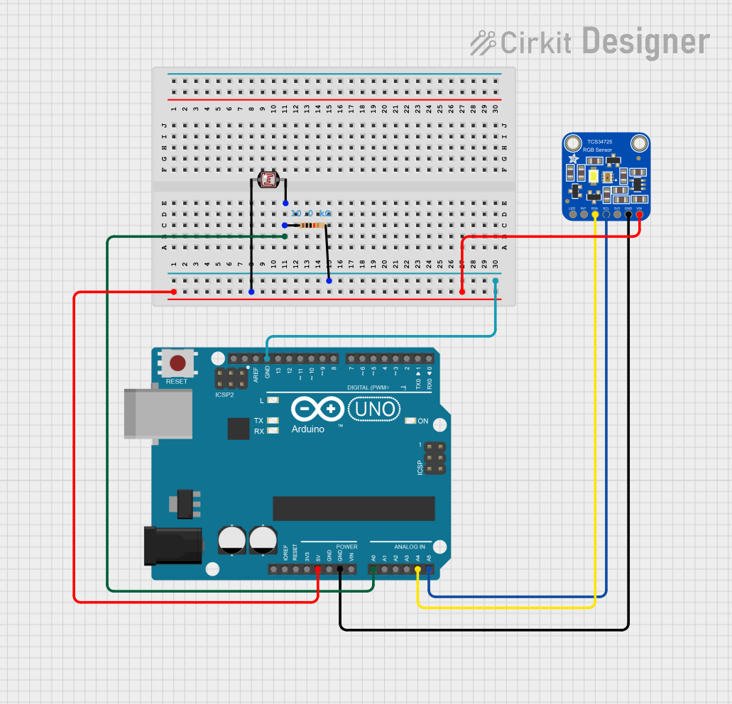
Circuit Documentation
Summary
The circuit in question is designed to interface an Adafruit TCS34725 RGB Color Sensor with an Arduino UNO microcontroller, along with a photocell (LDR) and a resistor to form a light-sensing module. The Arduino UNO serves as the central processing unit, reading data from the color sensor and the photocell, which can be used for applications such as color detection and ambient light sensing. The color sensor communicates with the Arduino via the I2C protocol, while the photocell's resistance varies with light intensity and is read through an analog input.
Component List
Adafruit TCS34725 RGB Color Sensor
- Description: A color sensor that can detect and measure a wide gamut of colors.
- Pins: LED_EN, INT, SDA, SCL, +3V3, GND, VIN
Arduino UNO
- Description: A microcontroller board based on the ATmega328P, widely used for building digital devices and interactive objects.
- Pins: UNUSED, IOREF, Reset, 3.3V, 5V, GND, Vin, A0-A5, SCL, SDA, AREF, D0-D13
Photocell (LDR)
- Description: A light-dependent resistor whose resistance changes with the amount of light falling on it.
- Pins: pin 0, pin 1
Resistor
- Description: A passive two-terminal electrical component that implements electrical resistance as a circuit element.
- Value: 10,000 Ohms (10kΩ)
Wiring Details
Adafruit TCS34725 RGB Color Sensor
- VIN connected to Arduino UNO 5V
- GND connected to Arduino UNO GND
- SDA connected to Arduino UNO A4 (SDA)
- SCL connected to Arduino UNO A5 (SCL)
Arduino UNO
- A0 connected to Photocell (LDR) pin 1 and Resistor pin1
- 5V connected to Photocell (LDR) pin 0 and Adafruit TCS34725 RGB Color Sensor VIN
- GND connected to Resistor pin2 and Adafruit TCS34725 RGB Color Sensor GND
- A4 (SDA) connected to Adafruit TCS34725 RGB Color Sensor SDA
- A5 (SCL) connected to Adafruit TCS34725 RGB Color Sensor SCL
Photocell (LDR)
- pin 0 connected to Arduino UNO 5V
- pin 1 connected to Arduino UNO A0 and Resistor pin1
Resistor
- pin1 connected to Photocell (LDR) pin 1 and Arduino UNO A0
- pin2 connected to Arduino UNO GND
Documented Code
Arduino UNO Code (sketch.ino)
void setup() {
  // put your setup code here, to run once:

}

void loop() {
  // put your main code here, to run repeatedly:

}
Note: The provided code is a template and does not include specific functionality. It needs to be populated with the initialization of the I2C interface, configuration of the TCS34725 sensor, and the logic to read and process data from the sensor and the photocell.