
Arduino-Controlled Robotics Platform with Dual DC Motor Drivers and Servo Actuation
View and Edit Project In Cirkit Designer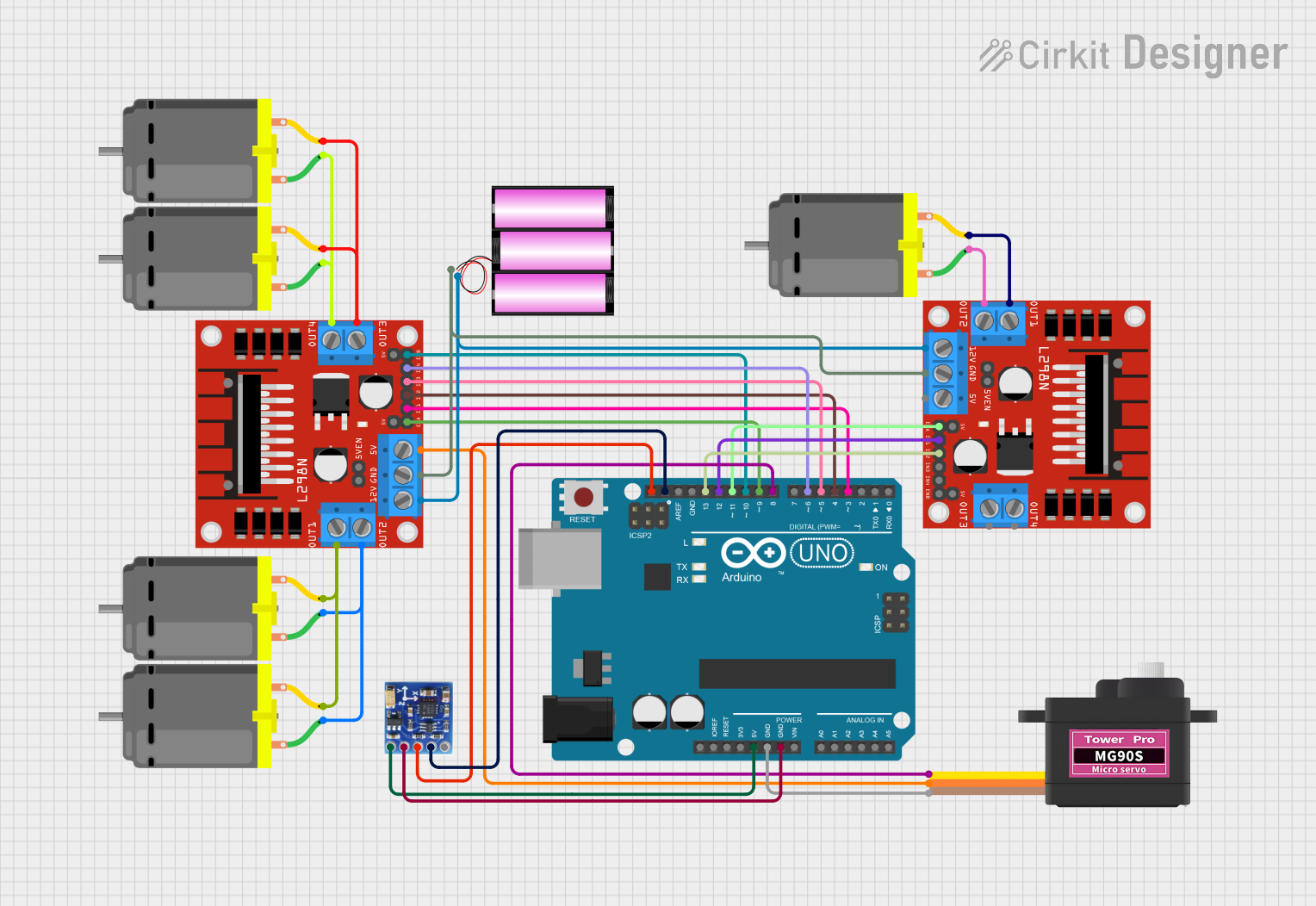
Circuit Documentation
Summary
This document provides a detailed overview of a circuit designed to control multiple DC motors using L298N motor drivers, an Arduino UNO microcontroller, a servomotor, and a QMC5883L magnetometer. The circuit is powered by a 12V battery and includes connections for power distribution, motor control signals, and I2C communication for the magnetometer.
Component List
L298N DC Motor Driver
- Description: A motor driver capable of driving a pair of DC motors.
- Pins: OUT1, OUT2, 12V, GND, 5V, OUT3, OUT4, 5V-ENA-JMP-I, 5V-ENA-JMP-O, +5V-J1, +5V-J2, ENA, IN1, IN2, IN3, IN4, ENB
DC Motor
- Description: A standard DC motor for rotational motion.
- Pins: pin 1, pin 2
Battery 12V
- Description: A 12V battery to provide power to the circuit.
- Pins: +, -
Arduino UNO
- Description: A microcontroller board based on the ATmega328P.
- Pins: UNUSED, IOREF, Reset, 3.3V, 5V, GND, Vin, A0, A1, A2, A3, A4, A5, SCL, SDA, AREF, D13, D12, D11, D10, D9, D8, D7, D6, D5, D4, D3, D2, D1, D0
Servomotor MG90S
- Description: A small and lightweight servomotor for precise control.
- Pins: SIG, VCC, GND
QMC5883L Magnetometer
- Description: A magnetometer sensor for detecting magnetic fields.
- Pins: VCC, GND, SCL, SDA, DRDY
Wiring Details
L298N DC Motor Driver
- 12V: Connected to the + pin of the 12V battery.
- GND: Connected to the - pin of the 12V battery and Arduino UNO GND.
- 5V: Connected to the VCC pin of the Servomotor MG90S.
- ENA, ENB: Controlled by Arduino UNO pins D11 and D10 respectively.
- IN1, IN2, IN3, IN4: Controlled by Arduino UNO pins D12, D13, D5, and D6 respectively.
- OUT1, OUT2, OUT3, OUT4: Connected to the pins of DC Motors.
DC Motor
- pin 1, pin 2: Connected to the OUT pins of the L298N DC Motor Drivers.
Arduino UNO
- 5V: Provides power to the QMC5883L Magnetometer.
- GND: Common ground for Servomotor MG90S and QMC5883L Magnetometer.
- SCL, SDA: I2C communication with QMC5883L Magnetometer.
- D13, D12, D11, D10, D9, D8, D6, D5, D4, D3: Control signals for L298N DC Motor Drivers and Servomotor MG90S.
Servomotor MG90S
- SIG: Controlled by Arduino UNO pin D8.
- VCC: Powered by the 5V output from one of the L298N DC Motor Drivers.
- GND: Connected to Arduino UNO GND.
QMC5883L Magnetometer
- VCC: Powered by Arduino UNO 5V.
- GND: Connected to Arduino UNO GND.
- SCL, SDA: I2C communication with Arduino UNO.
Documented Code
Arduino UNO Code (sketch.ino)
void setup() {
  // put your setup code here, to run once:

}

void loop() {
  // put your main code here, to run repeatedly:

}
Additional Notes
- The provided code is a template and does not contain any functional implementation for controlling the motors or reading from the magnetometer. The user is expected to fill in the setup and loop functions with the necessary code to initialize the motor drivers, servomotor, and magnetometer, and to implement the control logic for the application.
- The
documentation.txtfile is empty and can be used to add additional notes or documentation related to the code or circuit operation.