
Arduino UNO-Based Fire and Gas Leak Detection System with GSM Alert
View and Edit Project In Cirkit Designer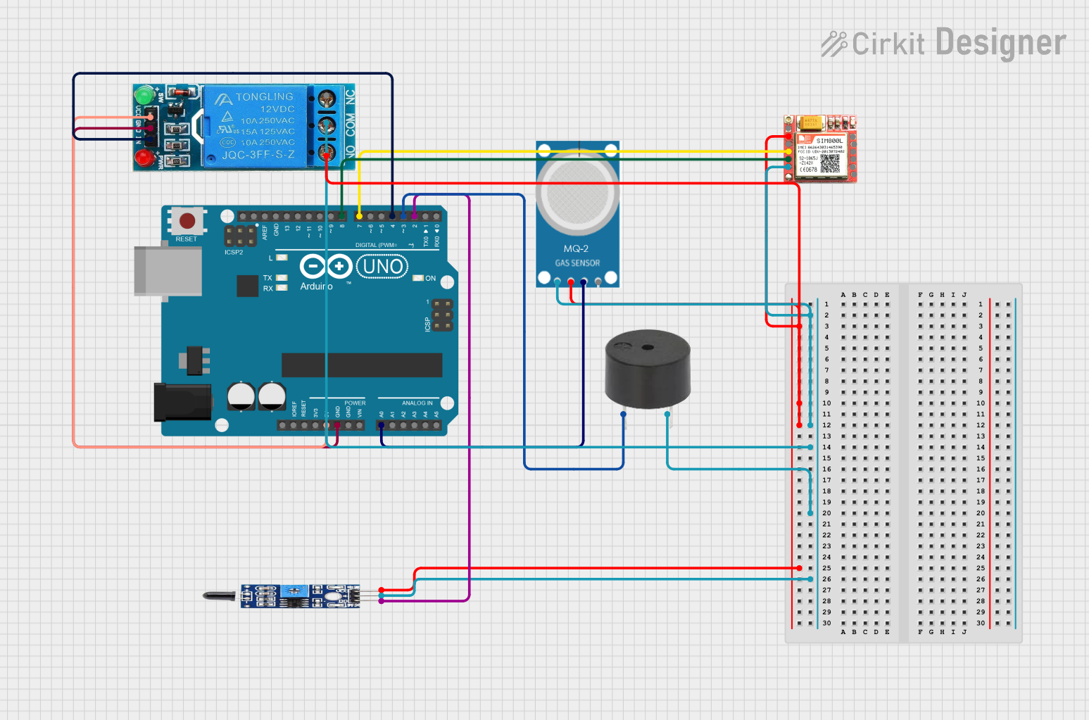
Circuit Documentation
Summary
This circuit is designed to detect gas leaks and fire, and then trigger an alarm and send an SMS notification using an Arduino UNO microcontroller. The circuit includes a gas sensor (MQ-2), a flame sensor, a SIM800L GSM module, a buzzer, and a 12V single-channel relay.
Component List
Arduino UNO
- Description: A microcontroller board based on the ATmega328P.
- Pins: UNUSED, IOREF, Reset, 3.3V, 5V, GND, Vin, A0, A1, A2, A3, A4, A5, SCL, SDA, AREF, D13, D12, D11, D10, D9, D8, D7, D6, D5, D4, D3, D2, D1, D0
Flame Sensor
- Description: A sensor used to detect the presence of fire or flame.
- Pins: VCC, GND, OUTPUT
MQ-2 Gas Sensor
- Description: A sensor used to detect gas leaks.
- Pins: GND, VCC, ANALOG, Digital
SIM800L GSM Module
- Description: A GSM module used to send SMS notifications.
- Pins: NFT, RING, VCC, DTR, RST, MIC +, RXD, MIC-, TXD, SPK+, GND, SPK-
Buzzer
- Description: An electronic device that emits a sound when activated.
- Pins: PIN, GND
12V Single Channel Relay
- Description: A relay module used to control high voltage devices.
- Pins: NC, COM, NO, IN, GND, VCC
Wiring Details
Arduino UNO
- 5V: Connected to VCC of the 12V Single Channel Relay.
- GND: Connected to GND of the 12V Single Channel Relay.
- A0: Connected to ANALOG of the MQ-2 Gas Sensor.
- D8: Connected to TXD of the SIM800L GSM Module.
- D7: Connected to RXD of the SIM800L GSM Module.
- D4: Connected to IN of the 12V Single Channel Relay.
- D3: Connected to PIN of the Buzzer.
- D2: Connected to OUTPUT of the Flame Sensor.
Flame Sensor
- VCC: Connected to VCC of the SIM800L GSM Module, MQ-2 Gas Sensor, and 12V Single Channel Relay.
- GND: Connected to GND of the SIM800L GSM Module, MQ-2 Gas Sensor, 12V Single Channel Relay, and Buzzer.
- OUTPUT: Connected to D2 of the Arduino UNO.
MQ-2 Gas Sensor
- GND: Connected to GND of the SIM800L GSM Module, 12V Single Channel Relay, Buzzer, and Flame Sensor.
- VCC: Connected to VCC of the SIM800L GSM Module, 12V Single Channel Relay, and Flame Sensor.
- ANALOG: Connected to A0 of the Arduino UNO.
SIM800L GSM Module
- GND: Connected to GND of the MQ-2 Gas Sensor, 12V Single Channel Relay, Buzzer, and Flame Sensor.
- VCC: Connected to VCC of the MQ-2 Gas Sensor, 12V Single Channel Relay, and Flame Sensor.
- TXD: Connected to D8 of the Arduino UNO.
- RXD: Connected to D7 of the Arduino UNO.
Buzzer
- PIN: Connected to D3 of the Arduino UNO.
- GND: Connected to GND of the SIM800L GSM Module, MQ-2 Gas Sensor, 12V Single Channel Relay, and Flame Sensor.
12V Single Channel Relay
- VCC: Connected to 5V of the Arduino UNO.
- GND: Connected to GND of the Arduino UNO.
- IN: Connected to D4 of the Arduino UNO.
- COM: Connected to GND of the SIM800L GSM Module, MQ-2 Gas Sensor, Buzzer, and Flame Sensor.
- NO: Connected to VCC of the SIM800L GSM Module, MQ-2 Gas Sensor, and Flame Sensor.
Code Documentation
#include <SoftwareSerial.h>

// Define pins
const int gasSensorPin = A0;
const int flameSensorPin = 2;
const int buzzerPin = 3;
const int relayPin = 4;

// Define GSM module pins
SoftwareSerial sim800l(7, 8); // RX, TX

// Threshold values (adjust as needed)
const int gasThreshold = 500; // Example value
const int flameThreshold = HIGH;

void setup() {
  Serial.begin(9600);
  sim800l.begin(9600);
  pinMode(flameSensorPin, INPUT);
  pinMode(buzzerPin, OUTPUT);
  pinMode(relayPin, OUTPUT);
}

void loop() {
  // Read gas sensor value
  int gasValue = analogRead(gasSensorPin);

  // Read flame sensor value
  int flameValue = digitalRead(flameSensorPin);

  // Check for gas leak
  if (gasValue > gasThreshold) {
    Serial.println("Gas leak detected!");
    triggerAlarm();
    sendSMS("Gas leak detected!");
  }

  // Check for fire
  if (flameValue == flameThreshold) {
    Serial.println("Fire detected!");
    triggerAlarm();
    sendSMS("Fire detected!");
  }

  delay(1000); // Check every second
}

void triggerAlarm() {
  digitalWrite(buzzerPin, HIGH);
  digitalWrite(relayPin, HIGH); // Activate relay (e.g., turn on fan)
  delay(1000);
  digitalWrite(buzzerPin, LOW);
  digitalWrite(relayPin, LOW);
  delay(1000);
}

void sendSMS(String message) {
  // Send SMS using SIM800L module
  sim800l.println("AT+CMGF=1");
  delay(1000);
  sim800l.println("AT+CMGS=\"+[Phone Number]\"\r");
  delay(1000);
  sim800l.print(message);
  delay(1000);
  sim800l.println((char)26);
  delay(5000);
}
This code initializes the sensors and the GSM module, reads the sensor values, and triggers an alarm and sends an SMS if gas or fire is detected. The triggerAlarm function activates the buzzer and the relay, while the sendSMS function sends an SMS using the SIM800L module.