Cirkit Designer
Your all-in-one circuit design IDE
Home /
Project Documentation
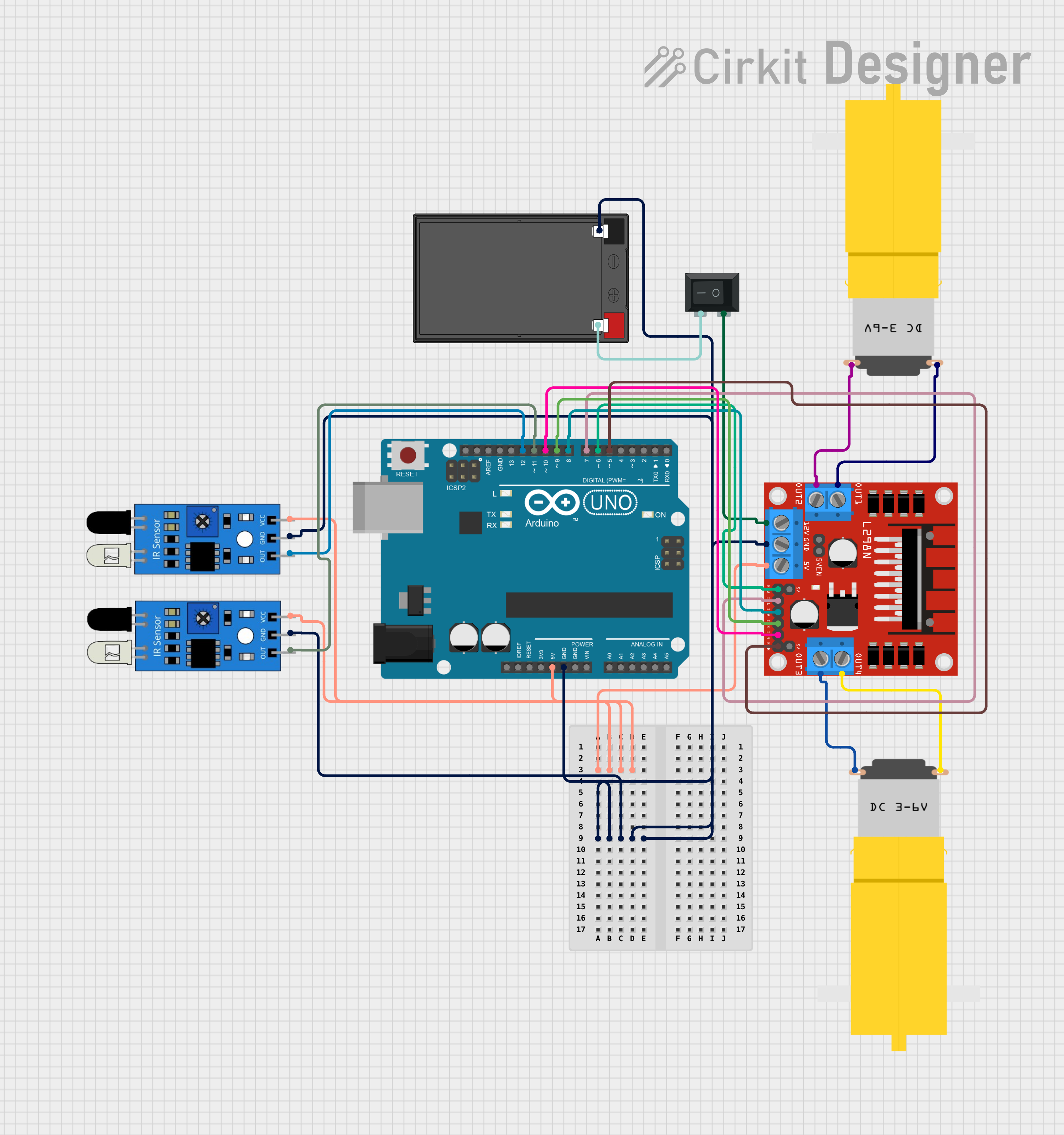
Arduino-Controlled Line-Following Robot with Dual IR Sensors and L298N Motor Driver
Circuit Documentation
Summary
This circuit is designed to control a pair of DC motors using an Arduino UNO microcontroller in conjunction with an L298N DC motor driver. The system also includes two infrared (IR) sensors for line tracking, which allows the robot to follow a path marked on the ground. A 12V 7Ah battery provides power to the system, and a rocker switch (SPST) is used to turn the power on and off.
Component List
Arduino UNO
- Microcontroller board based on the ATmega328P
- It has 14 digital input/output pins, 6 analog inputs, a 16 MHz quartz crystal, a USB connection, a power jack, an ICSP header, and a reset button.
L298N DC Motor Driver
- A dual H-bridge motor driver that can drive two DC motors or one stepper motor.
- It has pins for motor power supply, ground, control inputs, and motor outputs.
IR Sensors
- Used for line tracking by detecting the presence of a line or its absence.
- Each sensor has an output pin, ground, and Vcc for power.
DC Motors (Yellow Gear Motors)
- Hobbyist motors used for driving the wheels of the robot.
- Each motor has two pins for power supply and ground.
12V 7Ah Battery
- Provides the power source for the motor driver and indirectly for the motors.
- It has a positive and negative terminal.
Rocker Switch (SPST)
- A single-pole single-throw switch used to control the power supply to the circuit.
- It has two terminals for connecting the power source and the load.
Wiring Details
Arduino UNO
5VandGNDpins are connected to the power rails to provide power to the IR sensors and the L298N motor driver's logic.- Digital pins
D12andD11are connected to the output pins of the IR sensors for line tracking. - Digital pins
D10,D9,D8, andD7are connected to theIN4,IN3,IN2, andIN1pins of the L298N motor driver to control the motors. - Digital pins
D6andD5are connected to theENAandENBpins of the L298N motor driver to enable and control the speed of the motors.
L298N DC Motor Driver
5Vpin is connected to the 5V power rail.GNDpin is connected to the ground rail.12Vpin is connected to one terminal of the rocker switch to receive power from the battery.OUT1,OUT2,OUT3, andOUT4pins are connected to the respective motor terminals to drive the motors.
IR Sensors
Vccpins are connected to the 5V power rail.GNDpins are connected to the ground rail.Outpins are connected to the Arduino UNO digital pinsD12andD11for signal output.
DC Motors (Yellow Gear Motors)
- One terminal of each motor is connected to the
OUT1/OUT3pins of the L298N motor driver. - The other terminal of each motor is connected to the
OUT2/OUT4pins of the L298N motor driver.
12V 7Ah Battery
12v +terminal is connected to one terminal of the rocker switch.12v -terminal is connected to the ground rail.
Rocker Switch (SPST)
- One terminal is connected to the
12v +terminal of the battery. - The other terminal is connected to the
12Vpin of the L298N motor driver.
Documented Code
#define IR_SENSOR_RIGHT 11
#define IR_SENSOR_LEFT 12
#define MOTOR_SPEED 180

// Right motor
int enableRightMotor = 6;
int rightMotorPin1 = 7;
int rightMotorPin2 = 8;

// Left motor
int enableLeftMotor = 5;
int leftMotorPin1 = 9;
int leftMotorPin2 = 10;

void setup() {
  // Configure timer for PWM frequency adjustment
  TCCR0B = TCCR0B & B11111000 | B00000010;

  // Set motor control pins as outputs
  pinMode(enableRightMotor, OUTPUT);
  pinMode(rightMotorPin1, OUTPUT);
  pinMode(rightMotorPin2, OUTPUT);
  pinMode(enableLeftMotor, OUTPUT);
  pinMode(leftMotorPin1, OUTPUT);
  pinMode(leftMotorPin2, OUTPUT);

  // Set IR sensor pins as inputs
  pinMode(IR_SENSOR_RIGHT, INPUT);
  pinMode(IR_SENSOR_LEFT, INPUT);

  // Initialize motors to stop
  rotateMotor(0, 0);
}

void loop() {
  // Read IR sensor values
  int rightIRSensorValue = digitalRead(IR_SENSOR_RIGHT);
  int leftIRSensorValue = digitalRead(IR_SENSOR_LEFT);

  // Control logic based on sensor input
  if (rightIRSensorValue == LOW && leftIRSensorValue == LOW) {
    // Move forward
    rotateMotor(MOTOR_SPEED, MOTOR_SPEED);
  } else if (rightIRSensorValue == HIGH && leftIRSensorValue == LOW) {
    // Turn right
    rotateMotor(-MOTOR_SPEED, MOTOR_SPEED);
  } else if (rightIRSensorValue == LOW && leftIRSensorValue == HIGH) {
    // Turn left
    rotateMotor(MOTOR_SPEED, -MOTOR_SPEED);
  } else {
    // Stop
    rotateMotor(0, 0);
  }
}

void rotateMotor(int rightMotorSpeed, int leftMotorSpeed) {
  // Set motor direction and speed
  if (rightMotorSpeed < 0) {
    digitalWrite(rightMotorPin1, LOW);
    digitalWrite(rightMotorPin2, HIGH);
  } else if (rightMotorSpeed > 0) {
    digitalWrite(rightMotorPin1, HIGH);
    digitalWrite(rightMotorPin2, LOW);
  } else {
    digitalWrite(rightMotorPin1, LOW);
    digitalWrite(rightMotorPin2, LOW);
  }

  if (leftMotorSpeed < 0) {
    digitalWrite(leftMotorPin1, LOW);
    digitalWrite(leftMotorPin2, HIGH);
  } else if (leftMotorSpeed > 0) {
    digitalWrite(leftMotorPin1, HIGH);
    digitalWrite(leftMotorPin2, LOW);
  } else {
    digitalWrite(leftMotorPin1, LOW);
    digitalWrite(leftMotorPin2, LOW);
  }

  // Apply PWM to enable pins to control motor speed
  analogWrite(enableRightMotor, abs(rightMotorSpeed));
  analogWrite(enableLeftMotor, abs(leftMotorSpeed));
}
This code is responsible for reading the IR sensor inputs and controlling the motor speeds and directions accordingly. The rotateMotor function takes care of the motor control logic, setting the direction based on the sign of the speed value and using PWM to control the speed.