Cirkit Designer
Your all-in-one circuit design IDE
Home /
Project Documentation
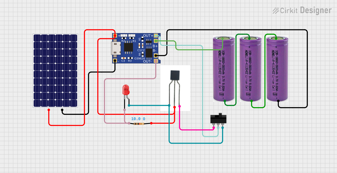
Solar-Powered LED Light with TP4056 Charging Module and Transistor Switch
Circuit Documentation
Summary of the Circuit
This circuit appears to be a charging and power supply system that uses a combination of solar panels and batteries to provide a stable 3.3V output. The TP4056 is a lithium battery charger and protection module that manages the charging of the battery from the solar panel and provides a regulated output. The circuit includes a toggle switch to control the power flow, a resistor to limit current, a BC557 transistor acting as a switch or amplifier, and an LED as an indicator or load.
Component List
3.3v Battery
- Description: A power source providing a nominal voltage of 3.3 volts.
- Purpose: To supply power to the circuit or to be charged by the TP4056 module when connected to a solar panel.
Resistor
- Description: A passive two-terminal electrical component that implements electrical resistance as a circuit element.
- Purpose: To limit the current flowing through the LED, protecting it from excessive current.
- Properties: 10 Ohms resistance.
TP4056
- Description: A lithium battery charger and protection module.
- Purpose: To charge the 3.3v battery using power from the solar panel and to provide a regulated output voltage.
BC557 Transistor
- Description: A PNP bipolar junction transistor.
- Purpose: To act as a switch or amplifier within the circuit, possibly controlling the LED or other loads.
Toggle Switch
- Description: An electrical switch that is manually actuated by a mechanical lever, handle, or rocking mechanism.
- Purpose: To allow the user to manually open or close the circuit, controlling the power flow to the load.
LED: Two Pin (red)
- Description: A two-pin light-emitting diode that emits red light.
- Purpose: To serve as an indicator light or as part of the load in the circuit.
Solar Panel
- Description: A panel designed to absorb the sun's rays as a source of energy for generating electricity.
- Purpose: To provide an alternative charging source for the 3.3v battery via the TP4056 module.
Wiring Details
3.3v Battery
+(Positive terminal): Connected to the B+ pin of the TP4056 module.-(Negative terminal): Connected to the B- pin of the TP4056 module.
Resistor
pin1: Connected to the cathode of the LED and the OUT- pin of the TP4056 module.pin2: Connected to the Base of the BC557 Transistor.
TP4056
OUT-: Connected to the cathode of the LED and pin1 of the Resistor.B-: Connected to the negative terminal of the 3.3v battery.B+: Connected to the positive terminal of the 3.3v battery.OUT+: Connected to the COM pin of the Toggle Switch.IN-: Connected to the negative pin of the solar panel.IN+: Connected to the positive pin of the solar panel and the Base of the BC557 Transistor through the Resistor.
BC557 Transistor
Collector: Connected to the L2 pin of the Toggle Switch and the anode of the LED.Base: Connected to the IN+ pin of the TP4056 module and pin2 of the Resistor.Emitter: Connected to the L1 pin of the Toggle Switch.
Toggle Switch
COM: Connected to the OUT+ pin of the TP4056 module.L1: Connected to the Emitter of the BC557 Transistor.L2: Connected to the Collector of the BC557 Transistor and the anode of the LED.
LED: Two Pin (red)
cathode: Connected to the OUT- pin of the TP4056 module and pin1 of the Resistor.anode: Connected to the Collector of the BC557 Transistor and the L2 pin of the Toggle Switch.
Solar Panel
+(Positive terminal): Connected to the IN+ pin of the TP4056 module and the Base of the BC557 Transistor through the Resistor.-(Negative terminal): Connected to the IN- pin of the TP4056 module.
Documented Code
There is no embedded code provided for any microcontrollers in this circuit. If there were microcontrollers and associated code, this section would detail the functionality and provide code annotations.