
Raspberry Pi Zero W-Based Security System with Motion Detection and Camera
View and Edit Project In Cirkit Designer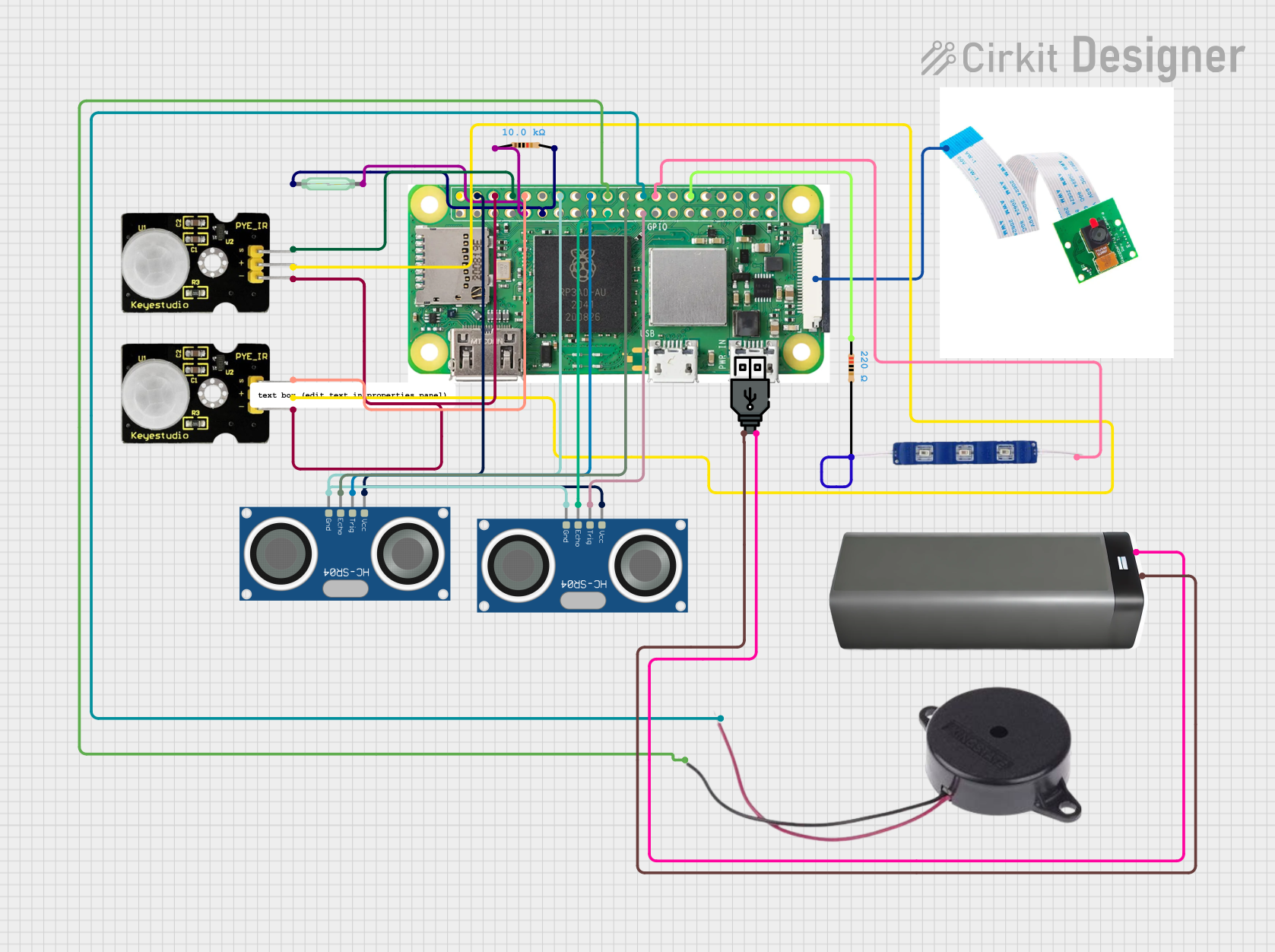
Circuit Documentation
Summary of the Circuit
This circuit is designed to function as a Raspberry Pi Zero W-based security system. It incorporates various sensors and devices to detect motion, measure distance, and provide visual and audible alerts. The system includes two PIR sensors for motion detection, two HC-SR04 ultrasonic sensors for distance measurement, a reed switch for magnetic field detection, a Raspberry Pi camera module for visual monitoring, a buzzer for audible alerts, and a 12V blue LED for visual indication. Power is supplied through a USB power connection linked to a battery pack.
Component List
Raspberry Pi Zero W
- A low-cost, compact variant of the Raspberry Pi with wireless LAN and Bluetooth connectivity.
- Pins: 5V, 3V3, multiple GPIOs, GND, CSI (Camera)
Resistor (10k Ohms)
- A passive two-terminal electrical component that implements electrical resistance as a circuit element.
Resistor (220 Ohms)
- A passive two-terminal electrical component that implements electrical resistance as a circuit element.
Reed Switch
- An electrical switch operated by an applied magnetic field.
Raspberry Pi Camera
- A small camera module compatible with the Raspberry Pi for taking photos and video.
HC-SR04 Ultrasonic Sensor (x2)
- An ultrasonic ranging module that provides 2cm to 400cm non-contact measurement functionality.
PIR Sensor (x2)
- A passive infrared sensor that measures infrared (IR) light radiating from objects in its field of view.
Buzzer
- An audio signaling device that can be mechanical, electromechanical, or piezoelectric.
USB Power
- A power supply module that provides power through a USB connection.
Battery Pack
- A pack of batteries providing a portable power source.
12V Blue LED
- A light-emitting diode that emits blue light when a voltage is applied.
Wiring Details
Raspberry Pi Zero W
- 5V connected to PIR Sensors (VCC) and HC-SR04 Ultrasonic Sensors (VCC)
- GROUND connected to PIR Sensors (GND), HC-SR04 Ultrasonic Sensors (GND), Buzzer (NEGATIVE), and Resistor (pin1)
- GPIO 14 connected to PIR Sensor (Data)
- GPIO 15 connected to PIR Sensor (Data)
- GPIO 17 connected to Reed Switch (pin 1)
- GPIO 24 connected to HC-SR04 Ultrasonic Sensor (TRIG)
- GPIO 25 connected to HC-SR04 Ultrasonic Sensor (ECHO)
- GPIO 8 connected to Buzzer (POSITIVE)
- GPIO 7 connected to 12V Blue LED (VCC)
- GPIO 10 connected to HC-SR04 Ultrasonic Sensor (ECHO)
- GPIO 11 connected to HC-SR04 Ultrasonic Sensor (TRIG)
- CSI (CAMERA) connected to Raspberry Pi Camera
Resistor (10k Ohms)
- pin1 connected to Raspberry Pi Zero W (GND)
- pin2 connected to Reed Switch (pin 2)
Resistor (220 Ohms)
- pin1 connected to Raspberry Pi Zero W (GND)
- pin2 connected to 12V Blue LED (GND)
Reed Switch
- pin 1 connected to Raspberry Pi Zero W (GPIO 17)
- pin 2 connected to Resistor (10k Ohms) (pin2)
HC-SR04 Ultrasonic Sensor
- VCC connected to Raspberry Pi Zero W (5V)
- TRIG connected to Raspberry Pi Zero W (GPIO 24 or GPIO 11)
- ECHO connected to Raspberry Pi Zero W (GPIO 25 or GPIO 10)
- GND connected to Raspberry Pi Zero W (GND)
PIR Sensor
- VCC connected to Raspberry Pi Zero W (5V)
- Data connected to Raspberry Pi Zero W (GPIO 14 or GPIO 15)
- GND connected to Raspberry Pi Zero W (GROUND)
Buzzer
- POSITIVE connected to Raspberry Pi Zero W (GPIO 8)
- NEGATIVE connected to Raspberry Pi Zero W (GND)
12V Blue LED
- VCC connected to Raspberry Pi Zero W (GPIO 7)
- GND connected to Resistor (220 Ohms) (pin2)
USB Power and Battery Pack
- "+" of USB Power connected to "+" of Battery Pack
- "-" of USB Power connected to "-" of Battery Pack
Documented Code
/*
 * Raspberry Pi Zero W-Based Security System
 * with PIR, Ultrasonic Sensors, and Camera
 *
 * This code controls a security system featuring:
 * - 2 PIR sensors for motion detection
 * - 2 HC-SR04 ultrasonic sensors for distance measurement
 * - 1 reed switch for magnetic field detection
 * - 1 Raspberry Pi camera module
 * - 1 buzzer for audible alerts
 * - 1 12V blue LED for visual indication
 *
 * Power is supplied through a USB power connection linked to a battery pack.
 */

// Pin definitions
const int PIR1_PIN = 14;
const int PIR2_PIN = 15;
const int REED_SWITCH_PIN = 17;
const int ULTRASONIC1_TRIG_PIN = 24;
const int ULTRASONIC1_ECHO_PIN = 25;
const int ULTRASONIC2_TRIG_PIN = 11;
const int ULTRASONIC2_ECHO_PIN = 10;
const int BUZZER_PIN = 8;
const int LED_PIN = 7;

void setup() {
  // Initialize serial communication
  Serial.begin(9600);

  // Initialize pins
  pinMode(PIR1_PIN, INPUT);
  pinMode(PIR2_PIN, INPUT);
  pinMode(REED_SWITCH_PIN, INPUT);
  pinMode(ULTRASONIC1_TRIG_PIN, OUTPUT);
  pinMode(ULTRASONIC1_ECHO_PIN, INPUT);
  pinMode(ULTRASONIC2_TRIG_PIN, OUTPUT);
  pinMode(ULTRASONIC2_ECHO_PIN, INPUT);
  pinMode(BUZZER_PIN, OUTPUT);
  pinMode(LED_PIN, OUTPUT);

  // Initialize camera (conceptual)
  // In practice, use Python or another language to control the camera
  // system("raspistill -o /home/pi/image.jpg");
}

void loop() {
  // Read PIR sensors
  bool pir1State = digitalRead(PIR1_PIN);
  bool pir2State = digitalRead(PIR2_PIN);

  // Read reed switch
  bool reedSwitchState = digitalRead(REED_SWITCH_PIN);

  // Read ultrasonic sensors
  long distance1 = readUltrasonic(ULTRASONIC1_TRIG_PIN, ULTRASONIC1_ECHO_PIN);
  long distance2 = readUltrasonic(ULTRASONIC2_TRIG_PIN, ULTRASONIC2_ECHO_PIN);

  // Check for motion or magnetic field
  if (pir1State || pir2State || reedSwitchState) {
    digitalWrite(BUZZER_PIN, HIGH);
    digitalWrite(LED_PIN, HIGH);

    // Capture image with camera (conceptual)
    // In practice, use Python or another language to control the camera
    // system("raspistill -o /home/pi/image.jpg");
  } else {
    digitalWrite(BUZZER_PIN, LOW);
    digitalWrite(LED_PIN, LOW);
  }

  // Print sensor values to serial monitor
  Serial.print("PIR1: "); Serial.print(pir1State);
  Serial.print(" PIR2: "); Serial.print(pir2State);
  Serial.print(" Reed: "); Serial.print(reedSwitchState);
  Serial.print(" Dist1: "); Serial.print(distance1);
  Serial.print(" Dist2: "); Serial.println(distance2);

  delay(1000); // Wait for 1 second
}

long readUltrasonic(int trigPin, int echoPin) {
  digitalWrite(trigPin, LOW);
  delayMicroseconds(2);
  digitalWrite(trigPin, HIGH);
  delayMicroseconds(10);
  digitalWrite(trigPin, LOW);
  long duration = pulseIn(echoPin, HIGH);
  long distance = duration * 0.034 / 2;
  return distance;
}
This code is designed to be uploaded to the Raspberry Pi Zero W and is written in the Arduino programming language (ino). It initializes the GPIO pins connected to the various sensors and devices, reads their states, and activates the buzzer and LED when motion or a magnetic field is detected. The ultrasonic sensors' distances are calculated and printed to the serial monitor. The camera control is conceptual and would typically be handled by a separate script in Python or another language.