
Arduino UNO Line-Following Robot with IR Sensors and Motor Control
View and Edit Project In Cirkit Designer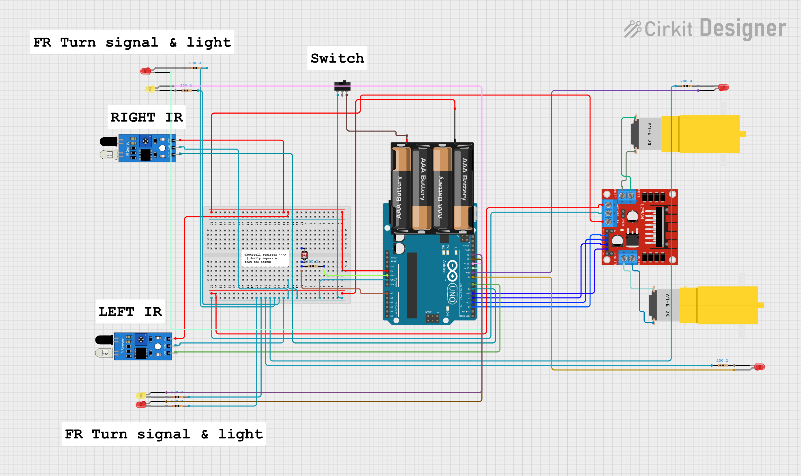
Circuit Documentation
Summary
This circuit is designed to control a robot using an Arduino UNO microcontroller. The robot is equipped with IR sensors for line following, motors for movement, LEDs for signaling, and a photocell for detecting ambient light levels. The circuit also includes a motor driver to control the motors and a battery mount for power supply.
Component List
Arduino UNO
- Description: Microcontroller board based on the ATmega328P.
- Pins: UNUSED, IOREF, Reset, 3.3V, 5V, GND, Vin, A0, A1, A2, A3, A4, A5, SCL, SDA, AREF, D13, D12, D11, D10, D9, D8, D7, D6, D5, D4, D3, D2, D1, D0
Motor amarillo motorreductor hobby
- Description: Hobby motor with gearbox.
- Pins: vcc, GND
L298N DC motor driver
- Description: Dual H-Bridge motor driver.
- Pins: OUT1, OUT2, 12V, GND, 5V, OUT3, OUT4, 5V-ENA-JMP-I, 5V-ENA-JMP-O, +5V-J1, +5V-J2, ENA, IN1, IN2, IN3, IN4, ENB
4 x AAA Battery Mount
- Description: Battery holder for 4 AAA batteries.
- Pins: -, +
IR Sensor
- Description: Infrared sensor for line detection.
- Pins: out, gnd, vcc
LED: Two Pin (red)
- Description: Red LED.
- Pins: cathode, anode
LED: Two Pin (yellow)
- Description: Yellow LED.
- Pins: cathode, anode
Toggle Switch
- Description: Toggle switch for user input.
- Pins: L1, COM, L2
Resistor
- Description: Resistor with a resistance of 200 Ohms.
- Pins: pin1, pin2
Photocell (LDR)
- Description: Light-dependent resistor.
- Pins: pin 0, pin 1
Wiring Details
Arduino UNO
GND is connected to:
- Resistor pin2
- Toggle Switch L1
- IR Sensor gnd (both sensors)
- L298N DC motor driver GND
5V is connected to:
- IR Sensor vcc (both sensors)
- L298N DC motor driver 5V
A0 is connected to:
- Resistor pin1
- Photocell (LDR) pin 1
D2 is connected to:
- L298N DC motor driver IN1
D3 is connected to:
- L298N DC motor driver IN2
D4 is connected to:
- L298N DC motor driver IN3
D5 is connected to:
- L298N DC motor driver IN4
D6 is connected to:
- IR Sensor out (first sensor)
D7 is connected to:
- IR Sensor out (second sensor)
D8 is connected to:
- LED (red) anode
D9 is connected to:
- LED (red) anode
D10 is connected to:
- LED (red) cathode
D11 is connected to:
- LED (yellow) anode
D12 is connected to:
- LED (red) anode
D13 is connected to:
- LED (yellow) anode
Motor amarillo motorreductor hobby
vcc is connected to:
- L298N DC motor driver OUT1 (first motor)
- L298N DC motor driver OUT3 (second motor)
GND is connected to:
- L298N DC motor driver OUT2 (first motor)
- L298N DC motor driver OUT4 (second motor)
L298N DC motor driver
12V is connected to:
- 4 x AAA Battery Mount -
GND is connected to:
- Arduino UNO GND
5V is connected to:
- Arduino UNO 5V
OUT1 is connected to:
- Motor amarillo motorreductor hobby vcc (first motor)
OUT2 is connected to:
- Motor amarillo motorreductor hobby GND (first motor)
OUT3 is connected to:
- Motor amarillo motorreductor hobby vcc (second motor)
OUT4 is connected to:
- Motor amarillo motorreductor hobby GND (second motor)
IN1 is connected to:
- Arduino UNO D2
IN2 is connected to:
- Arduino UNO D3
IN3 is connected to:
- Arduino UNO D4
IN4 is connected to:
- Arduino UNO D5
4 x AAA Battery Mount
- is connected to:
- L298N DC motor driver 12V
+ is connected to:
- Toggle Switch L2
IR Sensor
gnd is connected to:
- Arduino UNO GND
vcc is connected to:
- Arduino UNO 5V
out is connected to:
- Arduino UNO D6 (first sensor)
- Arduino UNO D7 (second sensor)
LED: Two Pin (red)
cathode is connected to:
- Arduino UNO D10
anode is connected to:
- Arduino UNO D8
- Arduino UNO D9
- Arduino UNO D12
LED: Two Pin (yellow)
cathode is connected to:
- Arduino UNO D10
anode is connected to:
- Arduino UNO D11
- Arduino UNO D13
Toggle Switch
L1 is connected to:
- Arduino UNO GND
L2 is connected to:
- 4 x AAA Battery Mount +
Resistor
pin1 is connected to:
- Arduino UNO A0
- Photocell (LDR) pin 1
pin2 is connected to:
- Arduino UNO GND
Photocell (LDR)
pin 0 is connected to:
- Resistor pin1
pin 1 is connected to:
- Arduino UNO A0
Documented Code
Arduino UNO Code
#include <LiquidCrystal_I2C.h>  // liquid crystal library

LiquidCrystal_I2C lcd(0x27, 16, 2);  // specifices how to refrence the LCD and it's characteristics

/*
 Tested Oct. 14
*/

// define variables

char array1[] = "Robot State:    ";
char array2[] = "STOPPED         ";
char array3[] = "FORWARD        ";
char array4[] = "BACKWARDS         ";
char array5[] = "RIGHT TURN    ";
char array6[] = "LEFT TURN    ";

#define leftIR 6
#define rightIR 7

#define LM1 2 // left motor 1
#define LM2 3 // left motor 2
#define RM1 4 // right motor 1
#define RM2 5 // right motor 2

#define FLturn 4 // Front Left Turn Signal
#define BLturn 4 // Back Left Turn Signal
#define FRturn 3 // Front Right Turn Signal
#define BRturn 3 // Back Right Turn Signal

#define Lbright 2 // Left brights
#define Rbright 1 // Right brights

#define photocellPin 13 // photocell resistor

#define ledpin 12;  //specify the LED pin to pin 12

int LCDprev = 99;   // helps to update the LCD state tracks previous
int LCDcurr = 100;  // helps to update the LCD state tracks current

int leftFlag; // used for debugging
int rightFlag; // used for debugging

// all necessary functions
void forward();
void leftTurn();
void rightTurn();
void reverse();
void stop();
void setup()
{
  lcd.init();       // initializes LCD
  lcd.backlight();  // turn on backlight

  pinMode(LM1, OUTPUT); // output pins for L298N for PWM funcionality
  pinMode(LM2, OUTPUT); // output pins for L298N for PWM funcionality
  pinMode(RM1, OUTPUT); // output pins for L298N for PWM funcionality
  pinMode(RM2, OUTPUT); // output pins for L298N for PWM funcionality

  pinMode(leftIR, INPUT); // Left IR sensor as an INPUT
  pinMode(rightIR, INPUT); // Right IR sensor as an INPUT
  digitalWrite(leftIR, HIGH); // output pins declared