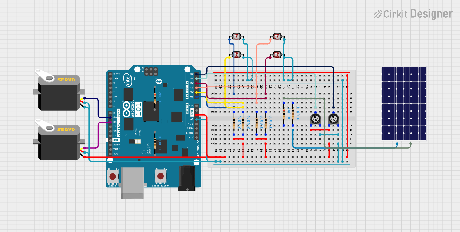
Arduino-Controlled Solar-Powered Light Tracking System

Circuit Documentation
Summary of the Circuit
This circuit appears to be designed to control two servo motors using an Arduino 101 microcontroller. The servos are powered by a common voltage supply, which is also connected to several photocells (LDRs) and trimmer potentiometers. The photocells are likely used for sensing light levels, and the potentiometers may be used for adjusting thresholds or setpoints in the circuit. The Arduino 101 is used to read the analog values from the photocells and potentiometers and to generate pulse-width modulation (PWM) signals to control the servos. Additionally, there are resistors in the circuit that may be used for voltage division or current limiting purposes.
Component List
Servo Motors
- Description: Servo motors are used for precise control of angular or linear position, velocity, and acceleration.
- Purpose: In this circuit, they are likely used for actuation based on sensor inputs.
Trimmer Potentiometers
- Description: A trimmer potentiometer is a small adjustable resistor.
- Purpose: These are typically used for adjusting a parameter in the circuit, such as a setpoint or threshold.
Resistors
- Description: Resistors are passive electrical components that create resistance in the flow of electric current.
- Purpose: In this circuit, they may be used for current limiting or forming voltage dividers.
Photocells (LDRs)
- Description: A photocell or light-dependent resistor (LDR) changes resistance based on the light intensity.
- Purpose: These are used as light sensors in the circuit.
Solar Panel
- Description: A solar panel converts light into electrical energy.
- Purpose: It may be used as a power source or for charging in this circuit.
Arduino 101
- Description: The Arduino 101 is a microcontroller board based on the Intel Curie Module.
- Purpose: It is used for processing sensor inputs and controlling other components like servos in the circuit.
Wiring Details
Servo Motors
- VCC: Connected to the 5V supply from the Arduino 101.
- GND: Connected to the common ground in the circuit.
- Pulse: Connected to the PWM-capable digital pins on the Arduino 101 (D9 PWM and D10 PWM/SS).
Trimmer Potentiometers
- Leg1: Connected to the common ground.
- Wiper: Connected to analog input pins on the Arduino 101 (A4/SDA and A5/SCL).
- Leg2: Connected to the 5V supply.
Resistors
- Pin1: Connected to various components such as the solar panel, Arduino analog inputs (A0 to A3), and photocells.
- Pin2: Connected to the common ground or solar panel.
Photocells (LDRs)
- Pin 0: Connected to the Arduino analog inputs (A0 to A3) through resistors.
- Pin 1: Connected to the 5V supply.
Solar Panel
- +: Connected to a resistor leading to the common ground.
- -: Connected to a resistor leading to the 5V supply.
Arduino 101
- 5V and GND: Provide power to the servos, photocells, and potentiometers.
- Analog Inputs (A0 to A5): Read values from the potentiometers and photocells.
- PWM Outputs (D9, D10): Control the servo motors.
Documented Code
There is no code provided for the microcontroller. The expected code would involve setting up the Arduino 101 to read analog inputs from the photocells and potentiometers, process the data, and then output PWM signals to control the servo motors based on the sensor inputs.