
TB6600 Stepper Motor Driver with CNC Control and Power Management
View and Edit Project In Cirkit Designer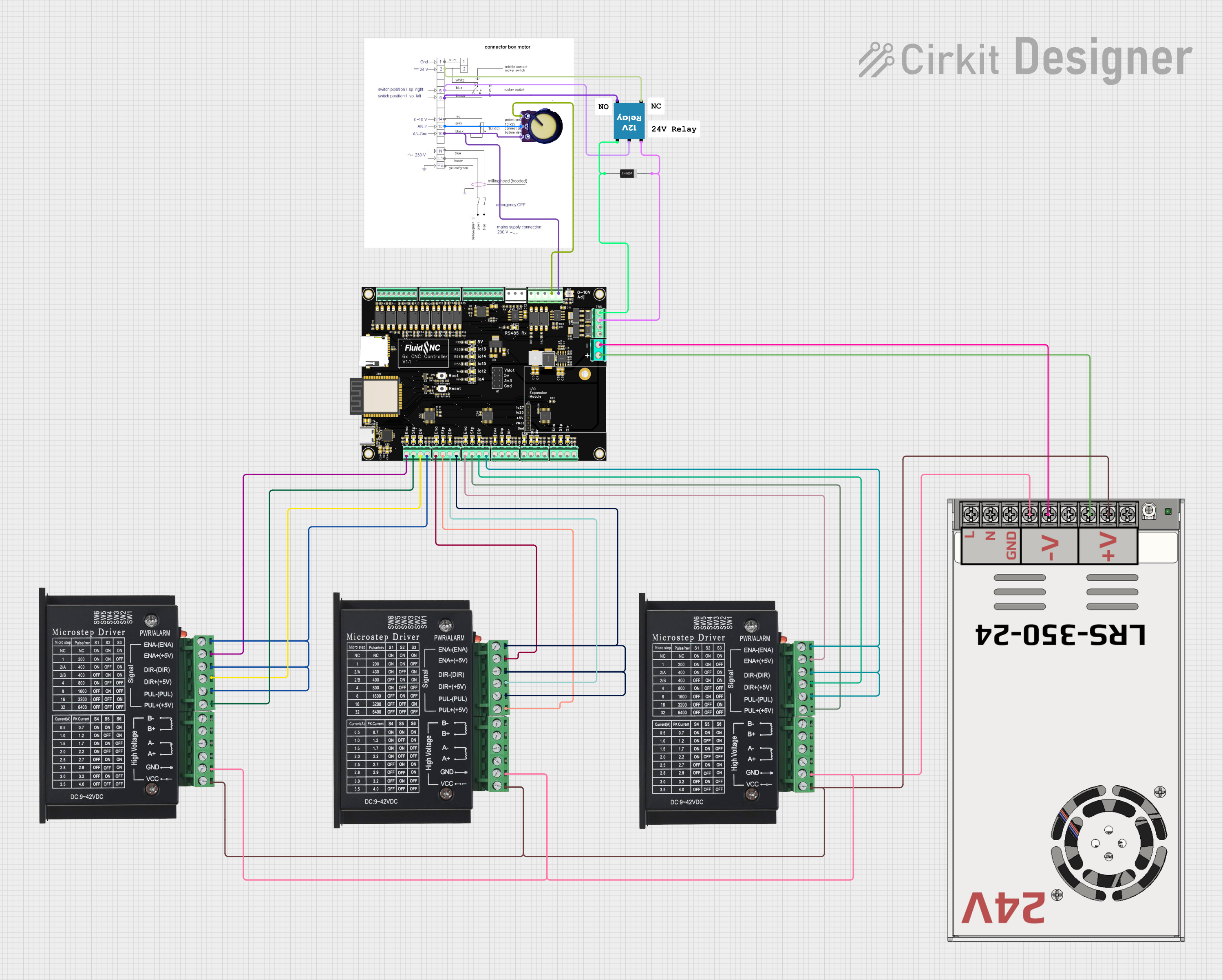
Circuit Documentation
Summary
The circuit in question appears to be designed for controlling a CNC machine with multiple stepper motor drivers (TB6600), a power supply (MW LRS-350-24), a relay module (12V Relay), a potentiometer for variable input, and a connector box for interfacing. The circuit does not include any microcontroller code, suggesting that the control logic might be handled externally or is yet to be developed.
Component List
TB6600 Stepper Motor Driver
- Description: A stepper motor driver that allows for control of one stepper motor. It has inputs for enabling, direction, and pulse signals, as well as outputs for the motor coils.
- Pins: ENA-, ENA+, DIR-, DIR+, PUL-, PUL+, B-, B+, A-, A+, GND, VCC
MW LRS-350-24 Power Supply
- Description: A 24V power supply unit that provides power to the circuit.
- Pins: +24V Output, -24V Output, GND, N, L
Connector Box
- Description: An interface box that provides connections for ground, power, control signals, and analog input.
- Pins: Gnd, VCC, Fwd, 0-10v, AN In, AN Gnd
12V Relay
- Description: An electromechanical switch that allows for control of high-power devices using low-power signals.
- Pins: +, -, C, NC, NO
6xCNC
- Description: Presumably a CNC controller board with multiple I/O pins for interfacing with various components such as stepper drivers and sensors.
- Pins: Multiple I/O pins including step, direction, enable for motor control, and RS485 communication pins.
1N4007 Rectifier Diode
- Description: A diode used for protecting the circuit from reverse voltage transients.
- Pins: Cathode, Anode
Potentiometer
- Description: A variable resistor that provides an adjustable voltage output.
- Pins: GND, Output, VCC
Comments
- Description: Placeholder components that may represent notes or unimplemented features in the circuit.
Wiring Details
TB6600 Stepper Motor Driver
- ENA-, DIR-, PUL- connected to respective GND pins on the 6xCNC controller.
- ENA+, DIR+, PUL+ connected to respective control pins on the 6xCNC controller for step, direction, and enable signals.
- GND connected to the -24V Output of the power supply.
- VCC connected to the +24V Output of the power supply.
MW LRS-350-24 Power Supply
- +24V Output provides power to the VCC pins of the TB6600 drivers and other components as required.
- -24V Output connected to the GND pins of the TB6600 drivers and other components as required.
Connector Box
- Gnd connected to the GND of the potentiometer and the Gnd of the 6xCNC controller.
- VCC connected to the NC pin of the 12V Relay.
- Fwd connected to the C pin of the 12V Relay.
- AN In connected to the Output of the potentiometer.
12V Relay
-
- connected to the VMot pin on the 6xCNC controller.
-
- connected to the io.12 pin on the 6xCNC controller and the Anode of the 1N4007 diode.
- NC connected to the VCC pin on the Connector Box.
- C connected to the Fwd pin on the Connector Box.
- NO not connected in the provided net list.
6xCNC
- Various I/O pins connected to the TB6600 drivers for motor control.
- VMot and Gnd pins connected to the power supply for motor voltage.
- RS485 communication pins for external communication (details not provided).
1N4007 Rectifier Diode
- Cathode connected to the + pin of the 12V Relay.
- Anode connected to the io.12 pin on the 6xCNC controller.
Potentiometer
- GND connected to the Gnd pin on the 6xCNC controller.
- Output connected to the AN In pin on the Connector Box.
- VCC connected to the Gnd pin on the 6xCNC controller (this may be an error in the net list, typically VCC should be connected to a positive voltage).
Documented Code
No code has been provided for the microcontrollers or any other programmable components in the circuit. The control logic and software implementation are either managed externally or are yet to be developed and integrated into the system.