
Circuit Documentation
Summary
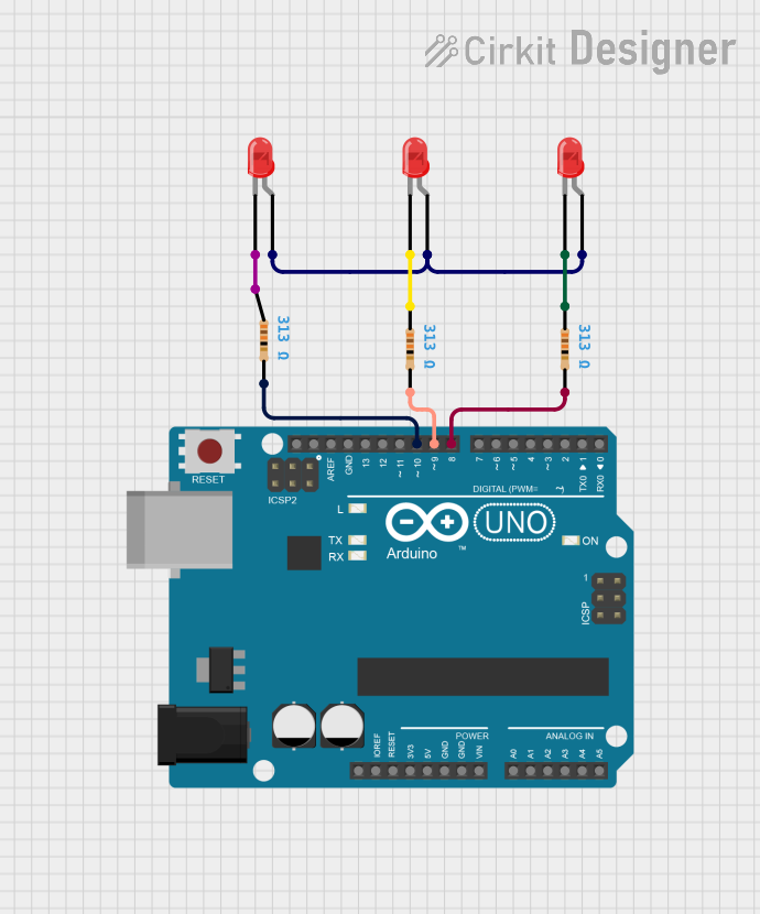
This circuit consists of three red two-pin LEDs, each paired with a 313-ohm resistor, and controlled by an Arduino UNO microcontroller. The LEDs are wired such that each one has its anode connected to a common node and its cathode connected through a resistor to a distinct digital output pin on the Arduino UNO. The microcontroller is programmed to sequentially turn on each LED for a duration of two seconds before moving on to the next LED.
Component List
LEDs
- LED: Two Pin (red)
- Description: A standard red LED with two pins: an anode and a cathode.
- Purpose: To emit red light when powered.
Resistors
- Resistor
- Description: A passive two-pin component with a resistance of 313 ohms.
- Purpose: To limit the current flowing through the LEDs, protecting them from damage.
Microcontroller
- Arduino UNO
- Description: A microcontroller board based on the ATmega328P, with a variety of digital and analog I/O pins.
- Purpose: To control the operation of the LEDs by providing power and enabling the blinking sequence.
Wiring Details
LED: Two Pin (red)
- Anode: Connected to a common node shared with the anodes of the other two LEDs.
- Cathode: Connected to one end of a 313-ohm resistor.
Resistor
- Pin1: Connected to the cathode of an LED.
- Pin2: Connected to a digital output pin on the Arduino UNO (D10, D9, or D8).
Arduino UNO
- D10, D9, D8: Each connected to the second pin of a 313-ohm resistor, controlling individual LEDs.
- Other Pins: Unused in this circuit.
Documented Code
// Code for controlling three LEDs with an Arduino UNO
// Each LED is connected to a digital pin through a 313-ohm resistor

void setup() {
  // Set the digital pins as outputs
  pinMode(10, OUTPUT);
  pinMode(9, OUTPUT);
  pinMode(8, OUTPUT);
}

void loop() {
  // Turn on the first LED (connected to D8)
  digitalWrite(8, HIGH);
  digitalWrite(9, LOW);
  digitalWrite(10, LOW);
  delay(2000); // Wait for 2 seconds

  // Turn on the second LED (connected to D9)
  digitalWrite(8, LOW);
  digitalWrite(9, HIGH);
  digitalWrite(10, LOW);
  delay(2000); // Wait for 2 seconds

  // Turn on the third LED (connected to D10)
  digitalWrite(8, LOW);
  digitalWrite(9, LOW);
  digitalWrite(10, HIGH);
  delay(2000); // Wait for 2 seconds
}
Filename: sketch.ino
This code is designed to sequentially light up three LEDs, each connected to a digital pin on the Arduino UNO (pins D8, D9, and D10). The setup() function initializes these pins as outputs. The loop() function then turns on each LED in turn, with a two-second delay between each LED. The digitalWrite() function is used to set the pin state to HIGH (LED on) or LOW (LED off).