Cirkit Designer
Your all-in-one circuit design IDE
Home /
Project Documentation
Arduino UNO Controlled Stepper Motor with Phototransistor and Pushbutton Inputs
Circuit Documentation
Summary
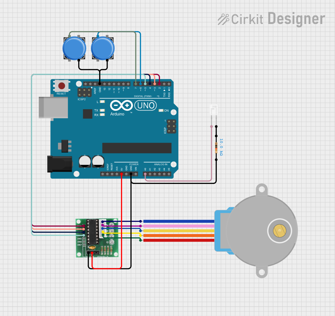
This circuit is designed to control a 28BYJ-48 stepper motor using an Arduino UNO. The motor is driven by a ULN2003 driver. The speed and direction of the motor are controlled by two pushbuttons. A phototransistor is used to detect light intensity and can be used to trigger motor actions based on light levels.
Component List
Arduino UNO
- Description: Microcontroller board based on the ATmega328P.
- Pins: UNUSED, IOREF, Reset, 3.3V, 5V, GND, Vin, A0, A1, A2, A3, A4, A5, SCL, SDA, AREF, D13, D12, D11, D10, D9, D8, D7, D6, D5, D4, D3, D2, D1, D0
Phototransistor
- Description: Light-sensitive transistor.
- Pins: C, E
28BYJ-48 Stepper Motor
- Description: 5V stepper motor.
- Pins: BLUE, PINK, YELLOW, ORANGE, RED
Pushbutton (1)
- Description: Momentary pushbutton switch.
- Pins: Pin 2, Pin 1, Pin 3, Pin 4
Pushbutton (2)
- Description: Momentary pushbutton switch.
- Pins: Pin 2, Pin 1, Pin 3, Pin 4
ULN 2003
- Description: High-voltage, high-current Darlington transistor array.
- Pins: IN1, IN2, IN3, IN4, IN5, IN6, IN7, GND, +, COIL1, COIL2, COIL3, COIL4, COIL5
Resistor
- Description: 10k Ohm resistor.
- Pins: pin1, pin2
- Properties: Resistance: 10k Ohms
Wiring Details
Arduino UNO
- 5V connected to + of ULN 2003
- GND connected to GND of ULN 2003 and pin2 of Resistor
- A0 connected to E of Phototransistor
- D7 connected to Pin 1 of Pushbutton (1)
- D6 connected to Pin 1 of Pushbutton (2)
- D5 connected to IN4 of ULN 2003
- D4 connected to IN3 of ULN 2003
- D3 connected to IN2 of ULN 2003
- D2 connected to IN1 of ULN 2003
Phototransistor
- E connected to A0 of Arduino UNO
- C connected to pin1 of Resistor
28BYJ-48 Stepper Motor
- BLUE connected to COIL1 of ULN 2003
- PINK connected to COIL2 of ULN 2003
- YELLOW connected to COIL3 of ULN 2003
- ORANGE connected to COIL4 of ULN 2003
- RED connected to COIL5 of ULN 2003
Pushbutton (1)
- Pin 1 connected to D7 of Arduino UNO
- Pin 4 connected to GND of Arduino UNO
Pushbutton (2)
- Pin 1 connected to D6 of Arduino UNO
- Pin 4 connected to GND of Arduino UNO
ULN 2003
- + connected to 5V of Arduino UNO
- GND connected to GND of Arduino UNO and pin2 of Resistor
- IN1 connected to D2 of Arduino UNO
- IN2 connected to D3 of Arduino UNO
- IN3 connected to D4 of Arduino UNO
- IN4 connected to D5 of Arduino UNO
- COIL1 connected to BLUE of 28BYJ-48 Stepper Motor
- COIL2 connected to PINK of 28BYJ-48 Stepper Motor
- COIL3 connected to YELLOW of 28BYJ-48 Stepper Motor
- COIL4 connected to ORANGE of 28BYJ-48 Stepper Motor
- COIL5 connected to RED of 28BYJ-48 Stepper Motor
Resistor
- pin1 connected to C of Phototransistor
- pin2 connected to GND of Arduino UNO and GND of ULN 2003
Documented Code
/*
 * Arduino UNO Controlled Stepper Motor with Phototransistor and Pushbutton Inputs
 *
 * This code controls a stepper motor using an Arduino UNO. The motor is driven
 * by a ULN2003 driver. The speed and direction of the motor are controlled by
 * two pushbuttons. A phototransistor is used to detect light intensity and can
 * be used to trigger motor actions based on light levels.
 */

#include <Stepper.h>

// Define the number of steps per revolution for the stepper motor
#define STEPS_PER_REV 2048

// Define pin connections
const int motorPin1 = 2; // IN1 on ULN2003 to D2 on Arduino
const int motorPin2 = 3; // IN2 on ULN2003 to D3 on Arduino
const int motorPin3 = 4; // IN3 on ULN2003 to D4 on Arduino
const int motorPin4 = 5; // IN4 on ULN2003 to D5 on Arduino
const int button1Pin = 6; // Pushbutton 1 to D6 on Arduino
const int button2Pin = 7; // Pushbutton 2 to D7 on Arduino
const int photoPin = A0; // Phototransistor to A0 on Arduino

// Initialize the stepper library
Stepper stepper(STEPS_PER_REV, motorPin1, motorPin3, motorPin2, motorPin4);

void setup() {
  // Set up the motor pins as outputs
  pinMode(motorPin1, OUTPUT);
  pinMode(motorPin2, OUTPUT);
  pinMode(motorPin3, OUTPUT);
  pinMode(motorPin4, OUTPUT);

  // Set up the button pins as inputs
  pinMode(button1Pin, INPUT);
  pinMode(button2Pin, INPUT);

  // Initialize serial communication for debugging
  Serial.begin(9600);
}

void loop() {
  // Read the state of the pushbuttons
  int button1State = digitalRead(button1Pin);
  int button2State = digitalRead(button2Pin);

  // Read the value from the phototransistor
  int photoValue = analogRead(photoPin);

  // Print the phototransistor value to the serial monitor
  Serial.print("Light Intensity: ");
  Serial.println(photoValue);

  // Control the stepper motor based on button states
  if (button1State == HIGH) {
    // Rotate the motor clockwise
    stepper.step(1);
  } else if (button2State == HIGH) {
    // Rotate the motor counterclockwise
    stepper.step(-1);
  }

  // Add a small delay to debounce the buttons
  delay(50);
}
This documentation provides a comprehensive overview of the circuit, including a summary, detailed component list, wiring details, and the code used to control the circuit.