
Circuit Documentation
Summary
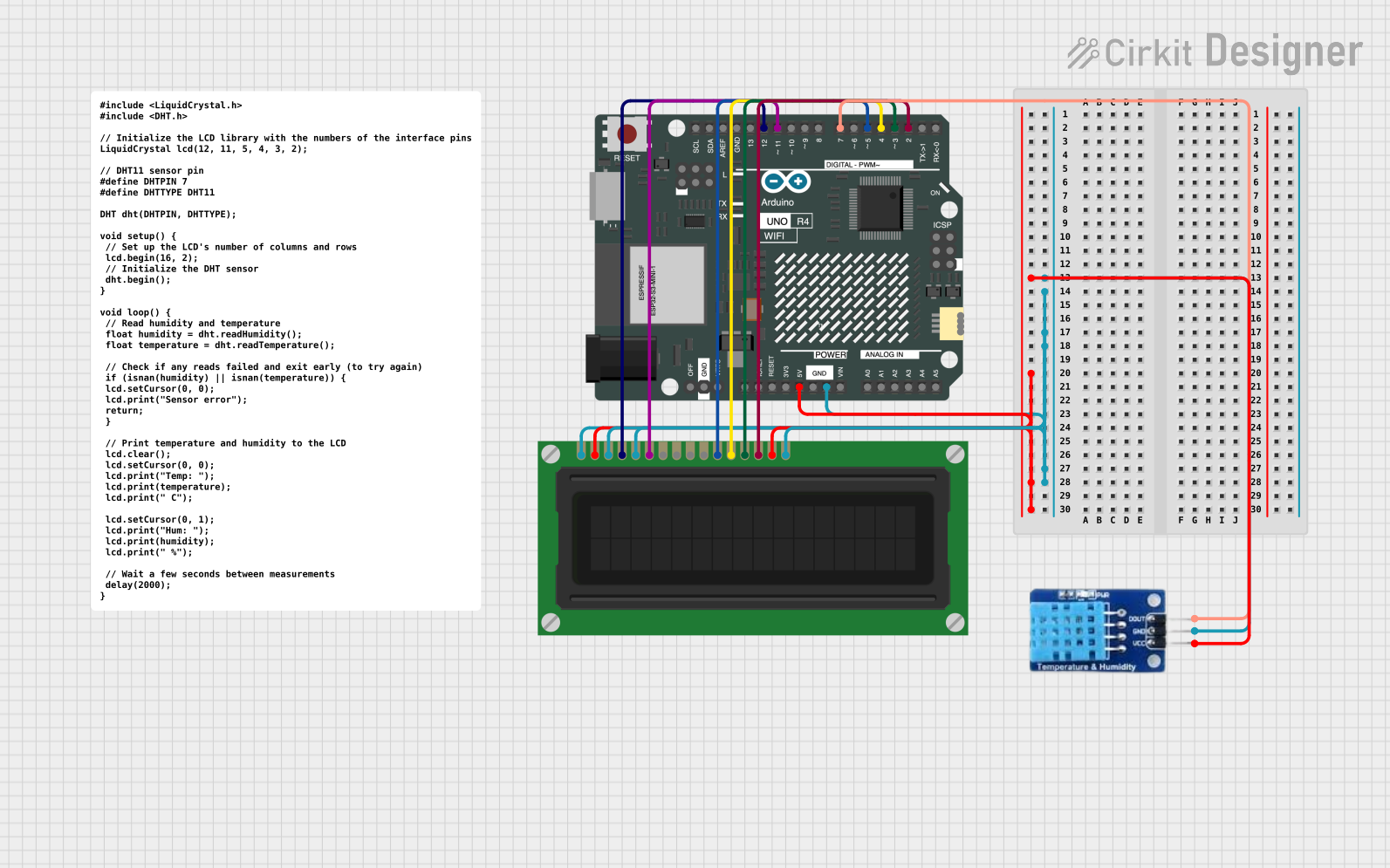
This circuit integrates an Arduino UNO R4 WiFi with an LCD Display and a DHT11 temperature and humidity sensor. The Arduino serves as the central microcontroller, interfacing with the LCD Display for output and the DHT11 sensor for environmental data input. The circuit is designed to be powered by the Arduino's 5V output, which is distributed to the other components.
Component List
Arduino UNO R4 WiFi
- Description: A microcontroller board based on the ATmega328, with integrated WiFi capabilities.
- Pins: OFF, GND, VRTC, IIC0_SCL, IIC0_SDA, 3V3, GPIO 41, GPIO 0, GPIO 42, GPIO 43, GPIO 44, BOOT, IOREF, RESET, 5V, VIN, A0, A1, A2, A3, A4, A5, RSPCKA, CIPO, COPI, D0/RX, D1/TX, D2, D3, D4, D5, D6, D7, D8, D9, D10, D11, D12, D13, AREF, SDA, SCL.
LCD Display (16 pin)
- Description: A 16-pin liquid crystal display for showing alphanumeric characters.
- Pins: VSS, VDD, VO, RS, R_W, E, DB0, DB1, DB2, DB3, DB4, DB5, DB6, DB7, A, K.
DHT11
- Description: A basic, ultra low-cost digital temperature and humidity sensor.
- Pins: DATA, GND, VCC.
Wiring Details
Arduino UNO R4 WiFi
- 5V to LCD Display VDD and A (backlight power)
- GND to LCD Display K (backlight ground), R_W (write select ground), VSS (ground), and VO (contrast adjustment)
- D2 to LCD Display DB7
- D3 to LCD Display DB6
- D4 to LCD Display DB5
- D5 to LCD Display DB4
- D7 to DHT11 DATA
- D11 to LCD Display E (enable)
- D12 to LCD Display RS (register select)
LCD Display (16 pin)
- VDD connected to 5V from Arduino
- VSS, R_W, and VO connected to GND from Arduino
- A (anode) connected to 5V from Arduino for backlight
- K (cathode) connected to GND from Arduino for backlight
- DB7 connected to Arduino D2
- DB6 connected to Arduino D3
- DB5 connected to Arduino D4
- DB4 connected to Arduino D5
- E connected to Arduino D11
- RS connected to Arduino D12
DHT11
- VCC connected to 5V from Arduino
- GND connected to GND from Arduino
- DATA connected to Arduino D7
Documented Code
Arduino UNO R4 WiFi Code (sketch.ino)
void setup() {
  // put your setup code here, to run once:

}

void loop() {
  // put your main code here, to run repeatedly:

}
Additional Notes
- The provided code is a template and does not include specific functionality. It needs to be populated with the logic for initializing the LCD display and reading data from the DHT11 sensor.
- The
setup()function is intended for initial configuration, and theloop()function will contain the main operational code that runs continuously. - The LCD display wiring assumes a 4-bit data interface with the Arduino. Additional code is required to control the LCD and display information.
- The DHT11 sensor's data pin is connected to the Arduino's digital pin D7. The code to read from the DHT11 sensor is not included and should be implemented in the
loop()function.