
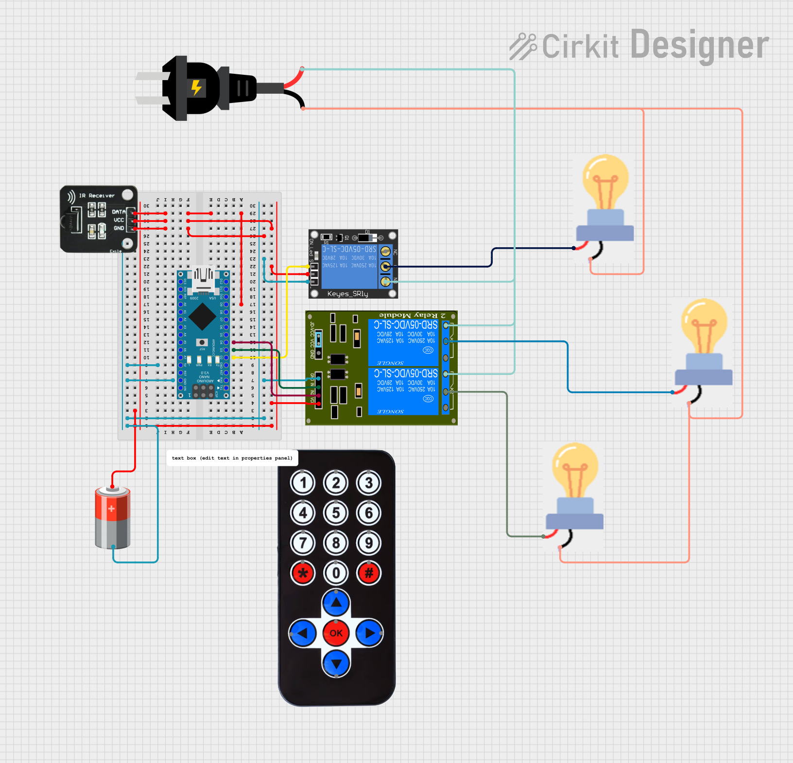
Circuit Documentation
Summary
This circuit is designed to control multiple relays and bulbs using an Arduino Nano and an IR remote control. The IR receiver captures signals from the remote, which the Arduino processes to control the relays. The relays, in turn, control the power to the bulbs. The circuit is powered by a 5V battery and an AC source.
Component List
Arduino Nano
- Description: A small, complete, and breadboard-friendly board based on the ATmega328P.
- Pins: D1/TX, D0/RX, RESET, GND, D2, D3, D4, D5, D6, D7, D8, D9, D10, D11/MOSI, D12/MISO, VIN, 5V, A7, A6, A5, A4, A3, A2, A1, A0, AREF, 3V3, D13/SCK
1-Channel Relay (5V 10A)
- Description: A relay module that can control high voltage, high current loads such as motors and lamps.
- Pins: NC, signal, C, power, NO, ground
2-Channel Relay (5V 10A)
- Description: A relay module with two channels, allowing control of two separate loads.
- Pins: K1-Off, K1-In, K2-On, K2-In, K1-On, K2-Off, VCC, JD-GND, IN2, IN1, GND
IR Receiver
- Description: A device that receives infrared signals from a remote control.
- Pins: DATA, VCC, GND
HX1838 Infrared IR Wireless Remote Control
- Description: A remote control that sends infrared signals to the IR receiver.
- Pins: FFA25D (1), FF629D (2), FFE21D (3), FF22DD (4), FF02FD (5), FFC23D (6), FFE01F (7), FFA857 (8), FF906F (9), FF9867 (0), FFB04F (#), FF6897 (*), FF18E7 (↑), FF5AA5 (→), FF10EF (←), FF4AB5 (↓), FF38C7 (OK)
Bulb
- Description: A standard light bulb.
- Pins: GND, power
AC Source
- Description: An alternating current power source.
- Pins: +, -
5V Battery
- Description: A battery providing 5V DC power.
- Pins: +, -
Wiring Details
Arduino Nano
- D9: Connected to DATA pin of the IR Receiver.
- D2: Connected to signal pin of the 1-Channel Relay.
- D3: Connected to IN1 pin of the 2-Channel Relay.
- D4: Connected to IN2 pin of the 2-Channel Relay.
- GND: Connected to GND pin of the 5V Battery.
- 5V: Connected to VCC pin of the 5V Battery.
1-Channel Relay (5V 10A)
- signal: Connected to D2 pin of the Arduino Nano.
- power: Connected to VCC pin of the 5V Battery.
- ground: Connected to GND pin of the 5V Battery.
- C: Connected to power pin of the Bulb.
- NO: Connected to + pin of the AC Source.
2-Channel Relay (5V 10A)
- IN1: Connected to D3 pin of the Arduino Nano.
- IN2: Connected to D4 pin of the Arduino Nano.
- VCC: Connected to VCC pin of the 5V Battery.
- GND: Connected to GND pin of the 5V Battery.
- K1-In: Connected to power pin of the Bulb.
- K2-In: Connected to power pin of the Bulb.
- K1-Off: Connected to + pin of the AC Source.
- K2-Off: Connected to + pin of the AC Source.
IR Receiver
- DATA: Connected to D9 pin of the Arduino Nano.
- VCC: Connected to VCC pin of the 5V Battery.
- GND: Connected to GND pin of the 5V Battery.
Bulbs
- power: Connected to C pin of the 1-Channel Relay.
- power: Connected to K1-In pin of the 2-Channel Relay.
- power: Connected to K2-In pin of the 2-Channel Relay.
- GND: Connected to - pin of the AC Source.
AC Source
- +: Connected to NO pin of the 1-Channel Relay.
- +: Connected to K1-Off pin of the 2-Channel Relay.
- +: Connected to K2-Off pin of the 2-Channel Relay.
- -: Connected to GND pin of the Bulbs.
5V Battery
- +: Connected to VCC pin of the IR Receiver, 1-Channel Relay, 2-Channel Relay, and Arduino Nano.
- -: Connected to GND pin of the IR Receiver, 1-Channel Relay, 2-Channel Relay, and Arduino Nano.
Code Documentation
#include <IRremote.h>

int IRpin = 9;
IRrecv IR(IRpin);
decode_results cmd;

int light1 = 2;
int fan1 = 3;
int light2 = 4;
int fan2 = 5;

void setup() {
  // put your setup code here, to run once:
  Serial.begin(9600);
  IR.enableIRIn();
  pinMode(light1, OUTPUT);
  pinMode(fan1, OUTPUT);
  pinMode(light2, OUTPUT);
  pinMode(fan2, OUTPUT);
}

void loop() {
  // put your main code here, to run repeatedly:
  while (IR.decode(&cmd) == 0) {
    // Wait for an IR command
  }
  Serial.println(cmd.value, HEX);
  delay(1000);
  IR.resume();

  if (cmd.value == 0xFFA25D) {
    digitalWrite(light1, LOW);
  }
  if (cmd.value == 0xFF629D) {
    digitalWrite(light1, HIGH);
  }

  if (cmd.value == 0xFF22DD) {
    digitalWrite(fan1, LOW);
  }
  if (cmd.value == 0xFF02FD) {
    digitalWrite(fan1, HIGH);
  }

  if (cmd.value == 0xFFE01F) {
    digitalWrite(light2, LOW);
  }
  if (cmd.value == 0xFFA857) {
    digitalWrite(light2, HIGH);
  }

  if (cmd.value == 0xFF6897) {
    digitalWrite(fan2, LOW);
  }
  if (cmd.value == 0xFF9867) {
    digitalWrite(fan2, HIGH);
  }
}
This code initializes the IR receiver and sets up the pins for the relays controlling the lights and fans. The loop function continuously checks for IR commands and toggles the corresponding relays based on the received command.