ESP32-Based Water Quality Monitoring System with LCD Display
Circuit Documentation
Summary
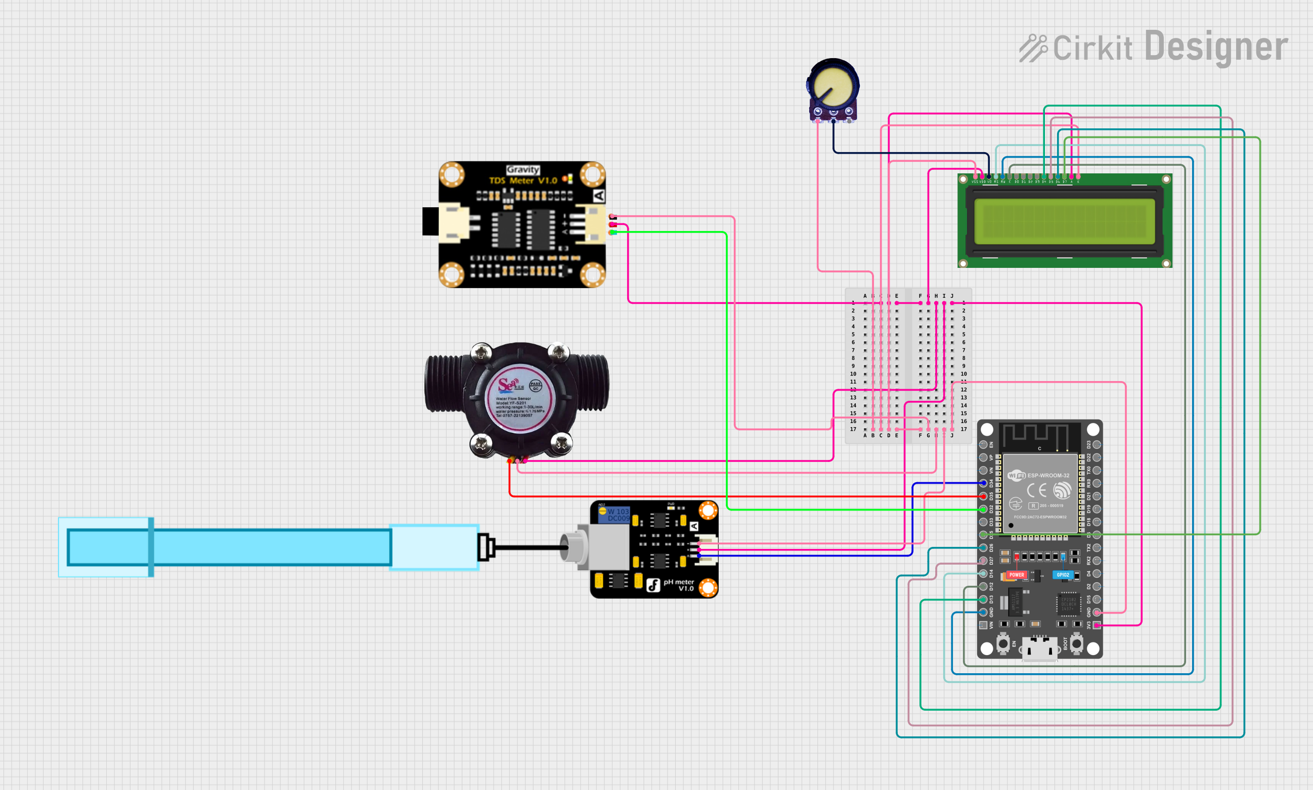
The circuit in question is designed to monitor various water quality parameters and display the results on an LCD screen. It includes sensors for measuring pH, water flow, and Total Dissolved Solids (TDS). The ESP32 microcontroller serves as the central processing unit, interfacing with the sensors and controlling the LCD display. The circuit is powered by a 3.3V supply, and a potentiometer is used for adjusting the contrast of the LCD display.
Component List
PH Meter
- Pins: Signal, VCC, GND
- Description: Measures the pH level of the water.
Water Flow Sensor
- Pins: Signal, Vcc, GND
- Description: Measures the flow rate of the water.
TDS Sensor Module
- Pins: TDS Negative, TDS Positive, TDS A
- Description: Measures the Total Dissolved Solids in the water.
LCD Display 16x2
- Pins: LEDK, LEDA, DB7-DB0, E, RW, RS, VO, VDD, VSS
- Description: Displays the measurements and other information.
ESP 32 DEVKIT V1 (30 pins)
- Pins: EN, VP, VN, D34-D23, GND, VIN, 3V3, RX0, TX0, RX2, TX2
- Description: Microcontroller that processes sensor data and controls the LCD display.
Potentiometer
- Pins: GND, Output, VCC
- Description: Adjusts the contrast of the LCD display.
Wiring Details
PH Meter
- Signal: Connected to ESP32 pin D34
- VCC: Connected to 3.3V power supply
- GND: Connected to ground
Water Flow Sensor
- Signal: Connected to ESP32 pin D35
- Vcc: Connected to 3.3V power supply
- GND: Connected to ground
TDS Sensor Module
- TDS Negative: Connected to ground
- TDS Positive: Connected to 3.3V power supply
- TDS A: Connected to ESP32 pin D32
LCD Display 16x2
- LEDK: Connected to ground
- LEDA: Connected to 3.3V power supply
- DB7: Connected to ESP32 pin D25
- DB6: Connected to ESP32 pin D26
- DB5: Connected to ESP32 pin D27
- DB4: Connected to ESP32 pin D13
- DB3-DB0: Not connected
- E: Connected to ESP32 pin D12
- RW: Connected to ground
- RS: Connected to ESP32 pin D14
- VO: Connected to Potentiometer Output
- VDD: Connected to 3.3V power supply
- VSS: Connected to ground
ESP 32 DEVKIT V1 (30 pins)
- 3V3: Power supply for the circuit (3.3V)
- GND: Ground connection for the circuit
- Digital Pins (D34, D35, D32, D25, D26, D27, D14, D12, D13): Connected to various sensors and LCD display as detailed above
Potentiometer
- GND: Connected to ground
- Output: Connected to LCD VO pin for contrast adjustment
- VCC: Connected to 3.3V power supply
Documented Code
No code has been provided for the microcontroller. The documentation of the code would typically include a description of the functionality, setup, and main loop, along with comments explaining the purpose of each function and variable. Since no code is available, this section cannot be completed at this time.