
Arduino Mega 2560 Controlled Multi-Stepper Motor System with SIM800L GSM Module
View and Edit Project In Cirkit Designer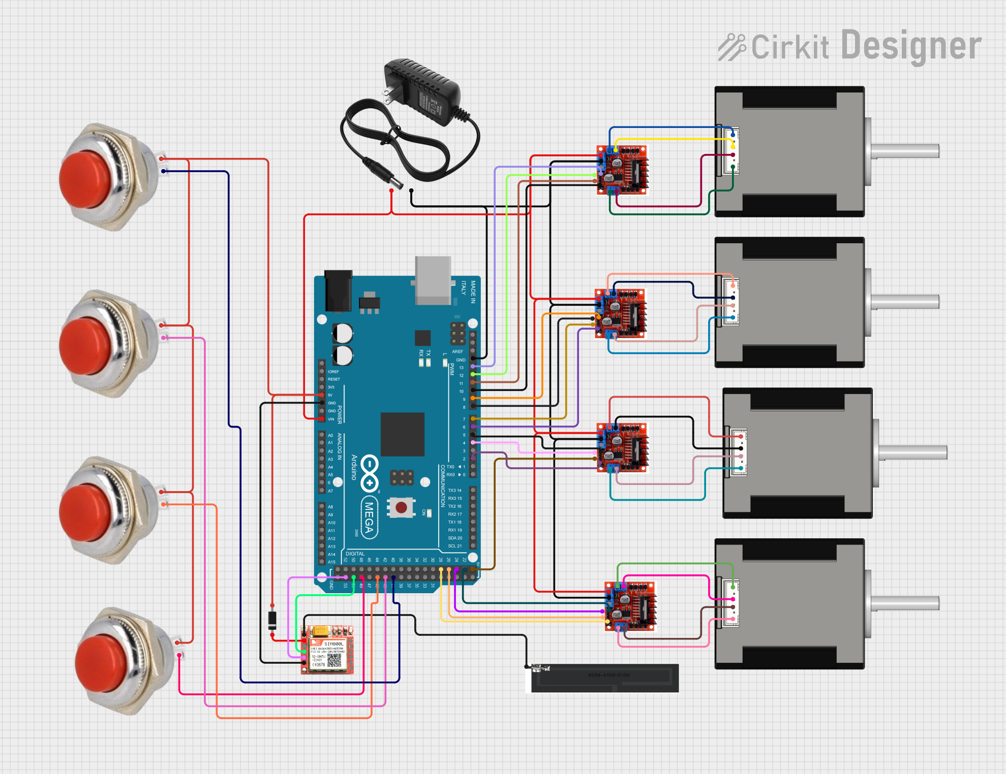
Circuit Documentation
Summary
This circuit is designed to control multiple stepper motors using L298N Motor Driver Controller Boards, which are interfaced with an Arduino Mega 2560 microcontroller. The circuit also includes a SIM800L module for cellular communication, diodes for voltage protection, PCB antennas for signal transmission, and momentary switches for user input. A 12V power supply is used to power the motor drivers and the Arduino Mega is powered through its VIN pin.
Component List
Microcontroller
- Arduino Mega 2560: A microcontroller board based on the ATmega2560, with a wide range of input/output pins, including PWM, analog, and digital pins.
Motor Drivers
- L298N Motor Driver Controller Board Module: Used to control the direction and speed of stepper motors. Each board can drive up to two motors.
Stepper Motors
- Nema 17 42-STH48: Bipolar stepper motors commonly used for precision control in CNC machines and 3D printers.
Power Supply
- 12V Power Supply: Provides the necessary power to the motor drivers and the Arduino Mega.
Communication Module
- SIM800L: A GSM/GPRS module that allows cellular network connectivity for voice calls, SMS, and data.
Diode
- Diode: Used for protecting the circuit from reverse voltage transients.
Antenna
- PCB Antenna: Used with the SIM800L module for cellular signal transmission.
Switches
- Red Momentary Switch 32 mm: User interface component for providing input to the microcontroller.
Wiring Details
Arduino Mega 2560
- 5V: Connected to the input of all momentary switches and the anode of the diode.
- GND: Common ground for the SIM800L module, motor drivers, and the 12V power supply.
- VIN: Connected to the +12V power line from the power supply.
- Digital Pins (D2, D4, D5, D6, D7, D8, D9, D10, D11, D12, D13, D22, D24, D26, D28, D41, D43, D45, D49, D51, D53): Control signals for the motor drivers and communication with the SIM800L module.
- PWM Pins (D2, D4, D5, D6, D7, D8, D9, D10, D11, D12, D13): Used to provide PWM signals to the motor drivers for speed control.
L298N Motor Driver Controller Boards
- +12V Power: Connected to the 12V power supply.
- Ground: Connected to the common ground.
- Input 1-4: Controlled by various PWM and digital pins from the Arduino Mega for motor direction and speed control.
- Output A/B: Connected to the corresponding wires of the Nema 17 stepper motors.
Nema 17 42-STH48 Stepper Motors
- A1 Green, A2 (black), B1 Blue, B2 Red: Connected to the outputs of the L298N motor drivers.
SIM800L Module
- GND: Connected to the common ground.
- VCC: Connected to the cathode of the diode for power.
- TXD, RXD: Communication with the Arduino Mega via digital pins D51 and D53.
- NFT: Connected to the PCB antenna for network signal transmission.
Diode
- Anode: Connected to the 5V output from the Arduino Mega.
- Cathode: Connected to the VCC of the SIM800L module.
PCB Antenna
- Wire: Connected to the NFT pin of the SIM800L module.
Red Momentary Switches 32 mm
- In: Connected to the 5V output from the Arduino Mega.
- Out: Connected to various digital pins on the Arduino Mega for user input detection.
Documented Code
Arduino Mega 2560 - sketch.ino
void setup() {
  // put your setup code here, to run once:

}

void loop() {
  // put your main code here, to run repeatedly:

}
Note: The provided code is a template and does not contain any functional code. It needs to be populated with the logic for controlling the motor drivers, reading the switches, and communicating with the SIM800L module.