
Arduino and NodeMCU ESP8266 Based Security Access Control System with RFID and Keypad
View and Edit Project In Cirkit Designer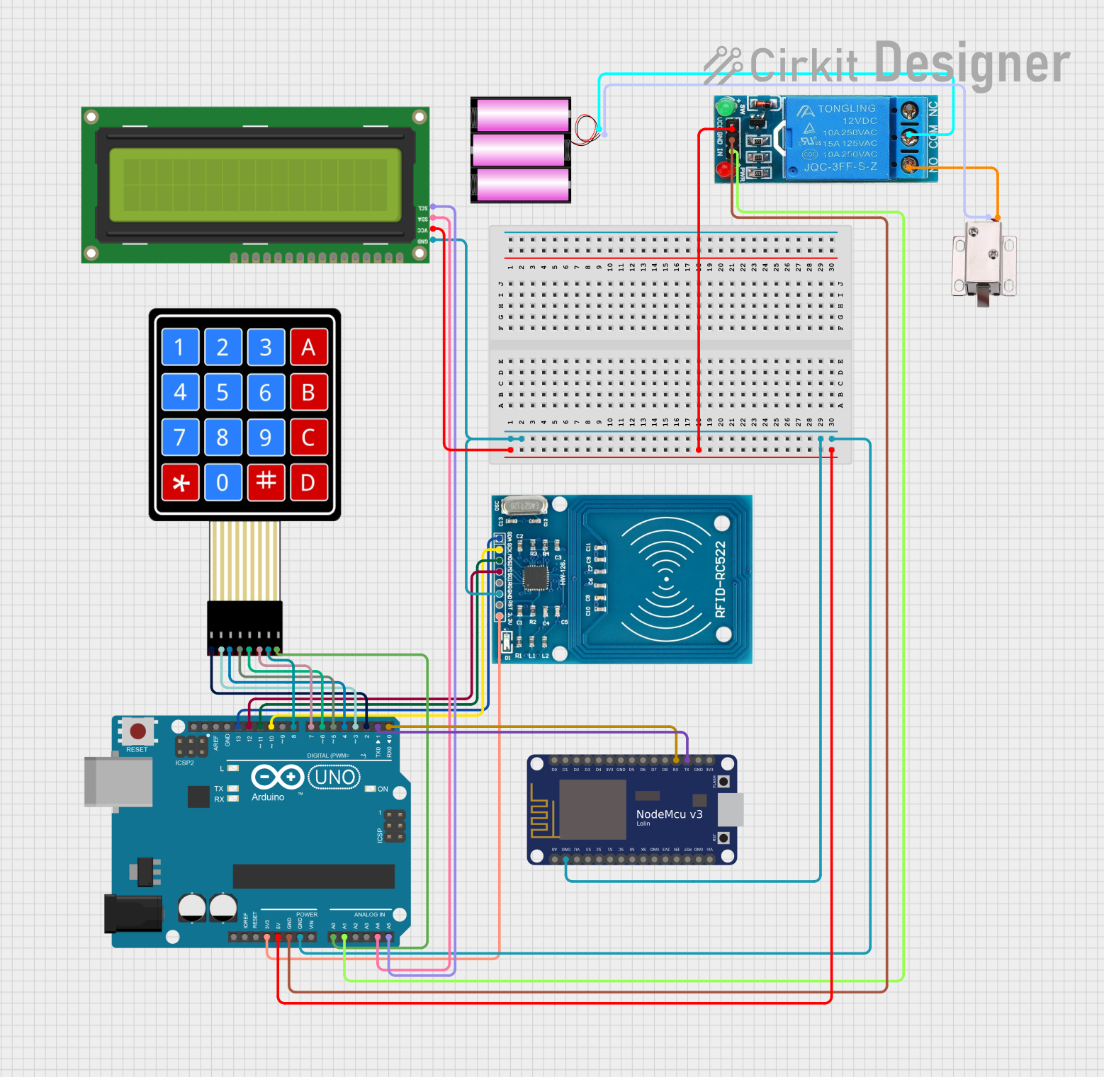
Circuit Documentation
Summary
This document provides a detailed overview of a circuit that integrates various components including an Arduino UNO, NodeMCU V3 ESP8266, a 12V battery, a 4x4 Membrane Matrix Keypad, an RFID-RC522 module, an I2C LCD 16x2 Screen, a 12V solenoid lock, and a 12V single-channel relay. The circuit is designed to perform tasks that likely involve user input through the keypad, RFID reading capabilities, display output on the LCD screen, and controlling access through the solenoid lock using the relay.
Component List
Arduino UNO
- Microcontroller board based on the ATmega328P
- Provides a range of digital and analog I/O pins
- Operates at 5V and has a 3.3V output pin
NodeMCU V3 ESP8266
- Wi-Fi enabled microcontroller module based on the ESP8266
- Offers multiple digital pins and a single analog input
- Can be used for IoT applications
Battery 12V
- Provides a 12V power source for components requiring higher voltage
- Typically used to power the solenoid lock and relay in this circuit
4X4 Membrane Matrix Keypad
- Input device with 16 buttons arranged in a 4x4 matrix
- Used for user input, such as entering a code for access control
RFID-RC522
- RFID reader/writer module operating at 13.56 MHz
- Used for contactless communication and identification
I2C LCD 16x2 Screen
- Alphanumeric liquid crystal display with 16 characters by 2 lines
- Utilizes the I2C communication protocol for displaying information
12V Solenoid Lock
- Electromechanical lock that operates at 12V
- Controlled by the relay to lock or unlock as needed
12V Single Channel Relay
- Electromechanical switch that can control high power devices
- Isolated by an optocoupler for safety and reliability
Wiring Details
Arduino UNO
3.3Vconnected to RFID-RC522 VCC (3.3V)5Vconnected to I2C LCD Screen VCC (5V) and 12V Single Channel Relay VCCGNDconnected to NodeMCU V3 ESP8266 GND, RFID-RC522 GND, I2C LCD Screen GND, and 12V Single Channel Relay GNDA0connected to 4X4 Membrane Matrix Keypad C4A1connected to 12V Single Channel Relay INA4connected to I2C LCD Screen SDAA5connected to I2C LCD Screen SCLD2toD13connected to various pins of the 4X4 Membrane Matrix Keypad and RFID-RC522D0andD1connected to NodeMCU V3 ESP8266 RX and TX respectively
NodeMCU V3 ESP8266
GNDconnected to Arduino UNO GNDRXconnected to Arduino UNO D0TXconnected to Arduino UNO D1
Battery 12V
+connected to 12V Single Channel Relay COM-connected to 12V Solenoid Lock GND
4X4 Membrane Matrix Keypad
R1toR4andC1toC4connected to Arduino UNO D2 to D9 respectively
RFID-RC522
VCC (3.3V)connected to Arduino UNO 3.3VGNDconnected to Arduino UNO GNDSDA,MISO,MOSI,SCKconnected to Arduino UNO D13, D12, D11, D10 respectively
I2C LCD 16x2 Screen
SDAconnected to Arduino UNO A4SCLconnected to Arduino UNO A5VCC (5V)connected to Arduino UNO 5VGNDconnected to Arduino UNO GND
12V Solenoid Lock
VCCconnected to 12V Single Channel Relay NOGNDconnected to Battery 12V -
12V Single Channel Relay
VCCconnected to Arduino UNO 5VGNDconnected to Arduino UNO GNDINconnected to Arduino UNO A1COMconnected to Battery 12V +NOconnected to 12V Solenoid Lock VCC
Documented Code
Arduino UNO Code (sketch.ino)
void setup() {
  // put your setup code here, to run once:

}

void loop() {
  // put your main code here, to run repeatedly:

}
Note: The provided code for the Arduino UNO is a template with empty setup and loop functions. The actual functionality needs to be implemented based on the specific requirements of the circuit.
NodeMCU V3 ESP8266 Code
No code provided for the NodeMCU V3 ESP8266.
End of Documentation