
How to Use HW-398: Examples, Pinouts, and Specs
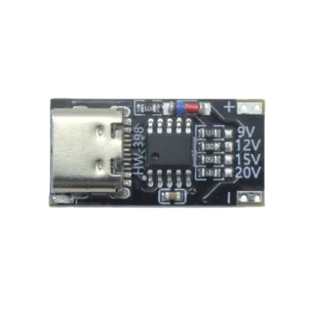
 Design with HW-398 in Cirkit Designer
Introduction
The HW-398, manufactured by Stas (Part ID: 2), is a versatile electronic component widely used in signal processing applications. Known for its reliability and efficiency, the HW-398 is a popular choice for engineers and hobbyists alike. Its compact design and robust performance make it suitable for a variety of circuits, including audio processing, communication systems, and general-purpose signal conditioning.
Explore Projects Built with HW-398
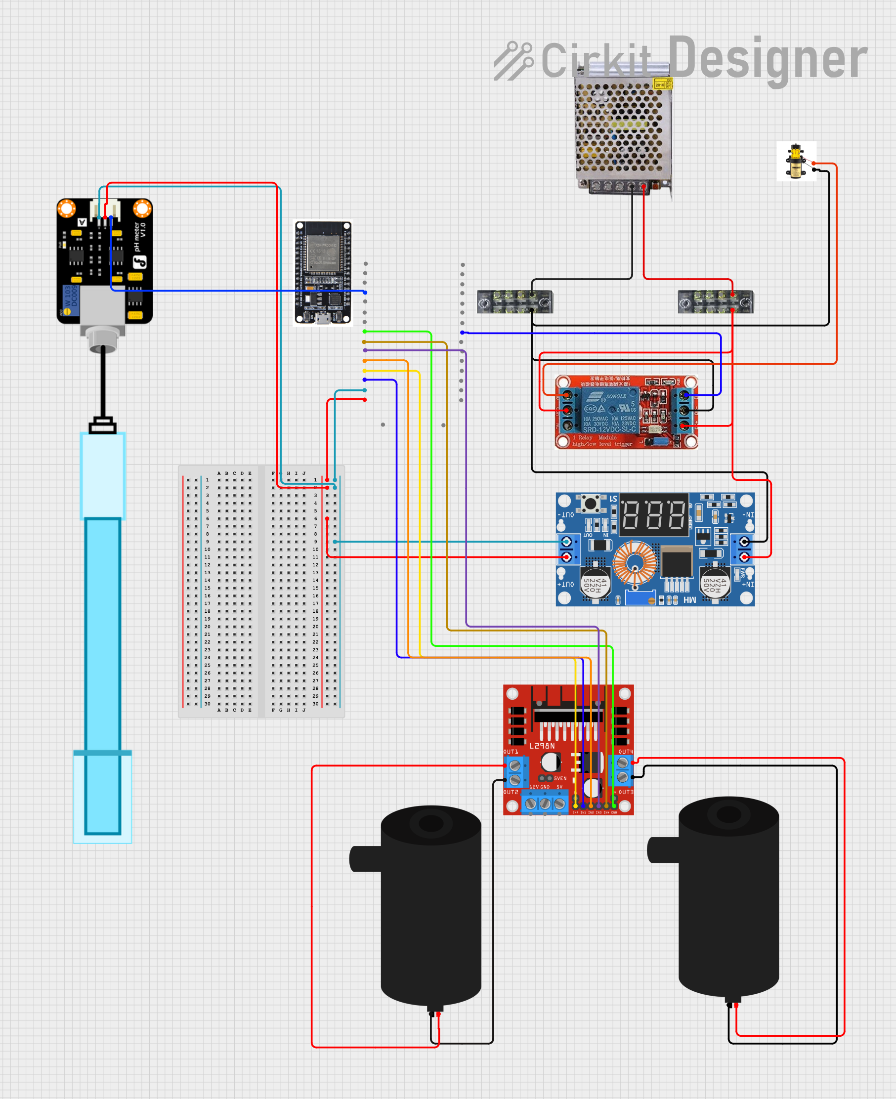 Open Project in Cirkit Designer
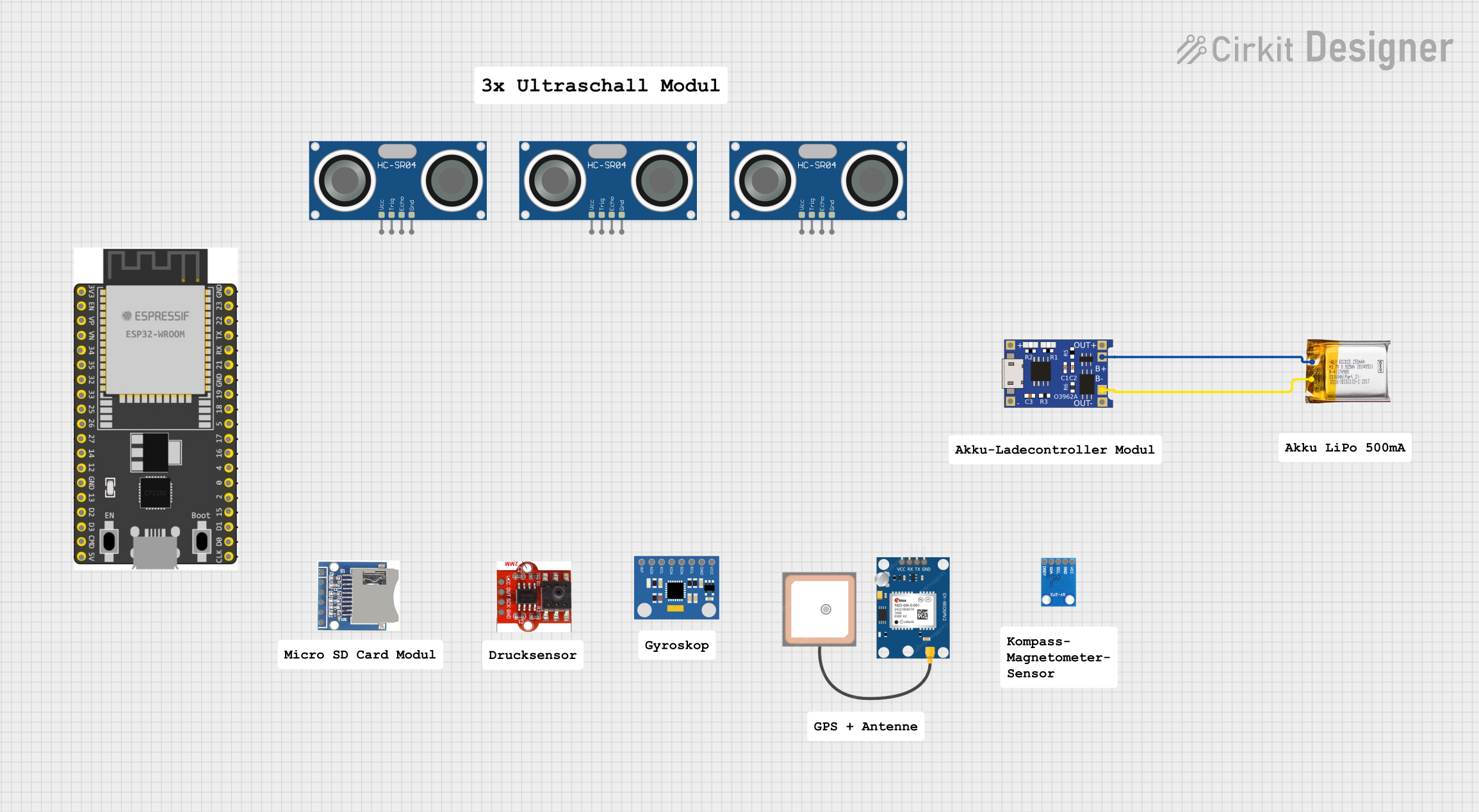 Open Project in Cirkit Designer
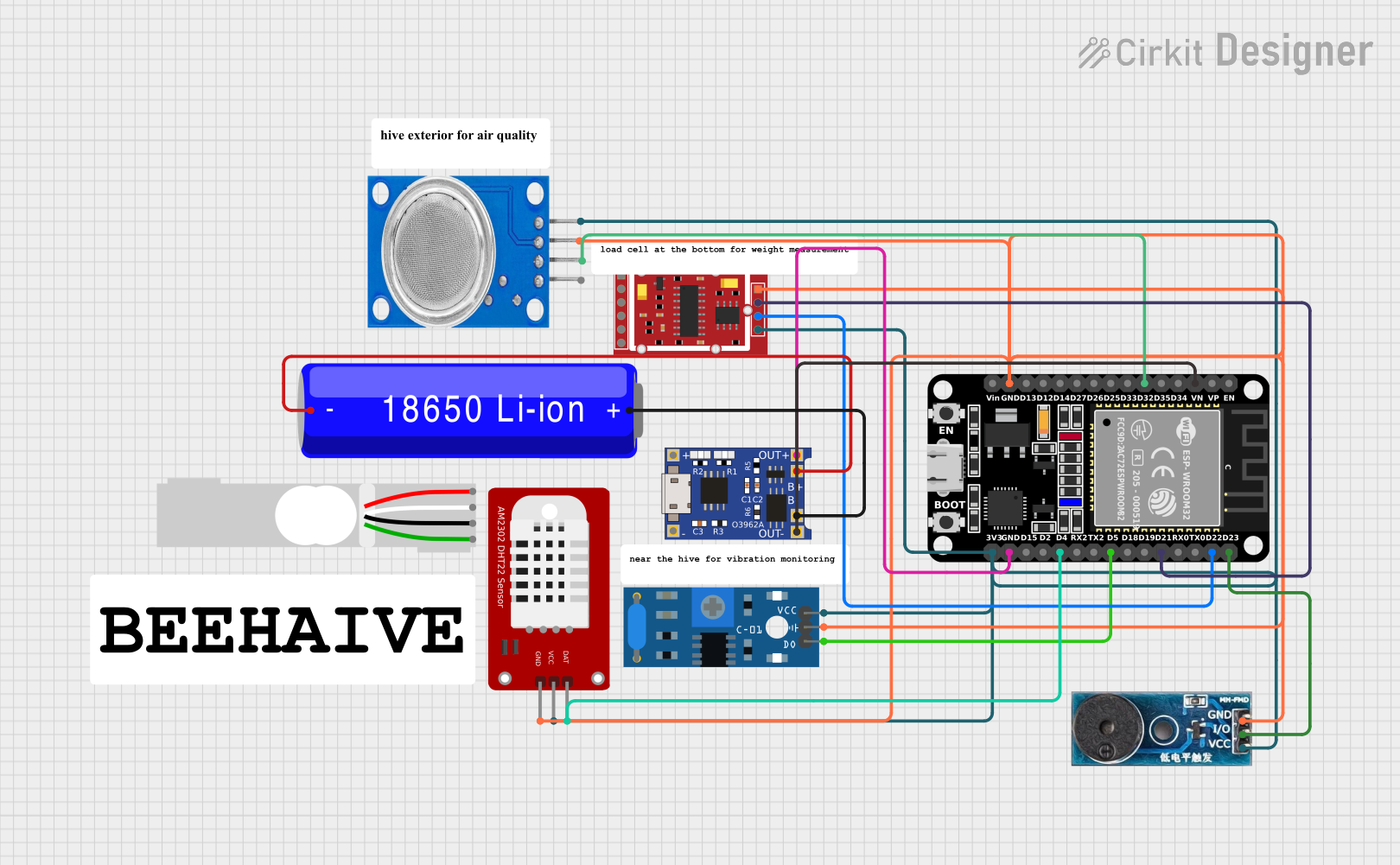 Open Project in Cirkit Designer
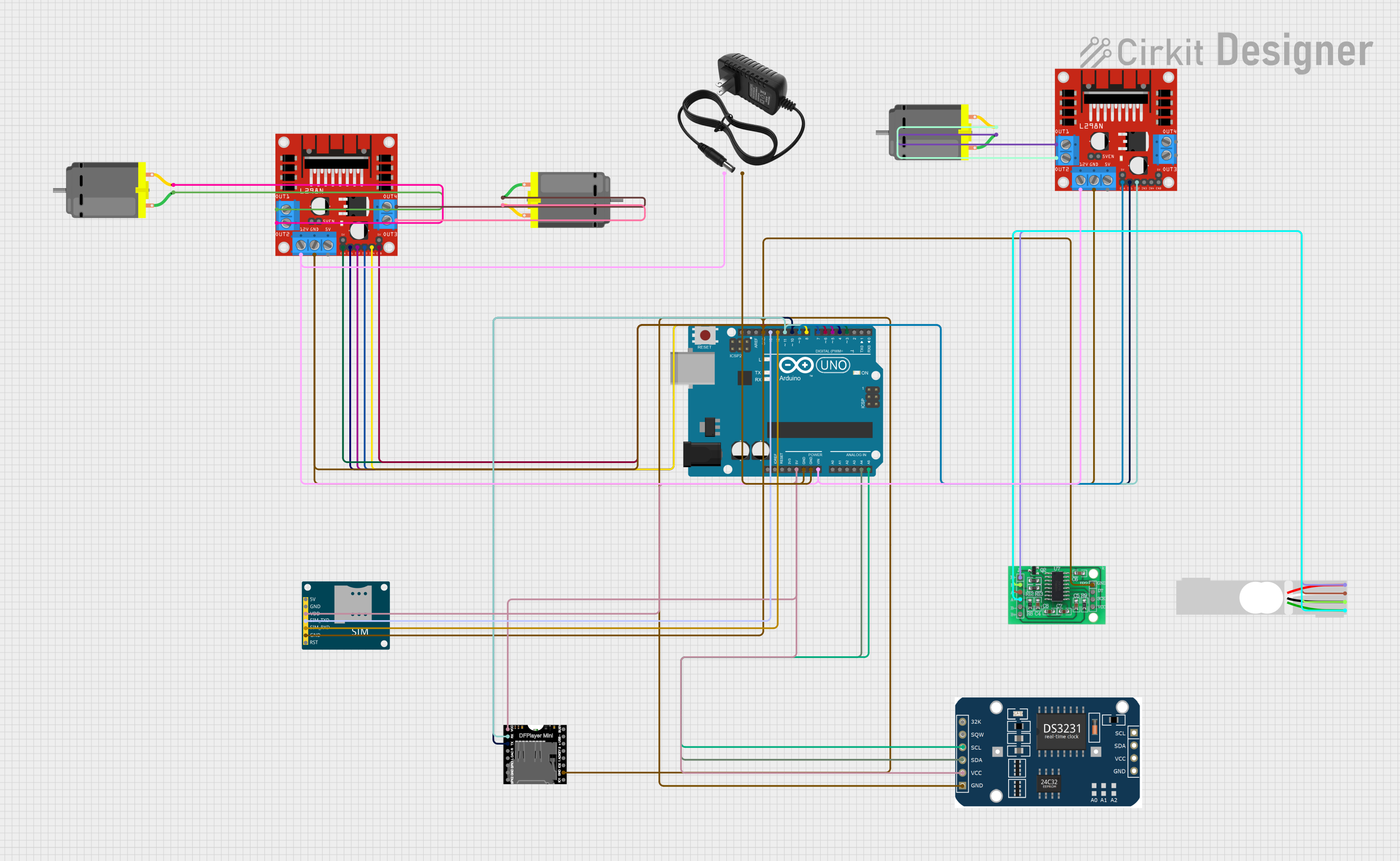 Open Project in Cirkit Designer
Explore Projects Built with HW-398
Open Project in Cirkit DesignerOpen Project in Cirkit DesignerOpen Project in Cirkit DesignerOpen Project in Cirkit DesignerCommon Applications
- Audio signal amplification and filtering
- Communication systems
- General-purpose signal processing
- Analog-to-digital interfacing
- Educational and prototyping projects
Technical Specifications
The HW-398 is designed to operate efficiently under a range of conditions. Below are its key technical details:
General Specifications
| Parameter | Value |
|---|---|
| Operating Voltage | 3.3V to 5V |
| Maximum Current | 20mA |
| Signal Frequency Range | 20Hz to 20kHz |
| Operating Temperature | -40°C to +85°C |
| Dimensions | 25mm x 15mm x 5mm |
Pin Configuration
The HW-398 features a simple pinout for easy integration into circuits. Below is the pin configuration:
| Pin Number | Pin Name | Description |
|---|---|---|
| 1 | VCC | Power supply input (3.3V to 5V) |
| 2 | GND | Ground connection |
| 3 | IN | Signal input |
| 4 | OUT | Signal output |
| 5 | NC | Not connected (leave unconnected or floating) |
Usage Instructions
The HW-398 is straightforward to use in a variety of circuits. Follow the steps below to integrate it into your project:
Basic Circuit Setup
- Power Supply: Connect the
VCCpin to a 3.3V or 5V power source and theGNDpin to the ground of your circuit. - Signal Input: Feed the input signal to the
INpin. Ensure the signal voltage does not exceed the operating voltage range. - Signal Output: The processed signal will be available at the
OUTpin. Connect this pin to the next stage of your circuit (e.g., an amplifier or microcontroller ADC). - Unused Pin: Leave the
NCpin unconnected.
Important Considerations
- Power Supply Stability: Use a decoupling capacitor (e.g., 0.1µF) between
VCCandGNDto ensure stable operation. - Signal Integrity: Avoid feeding high-frequency noise into the
INpin to maintain signal quality. - Temperature Range: Operate the HW-398 within its specified temperature range to prevent damage.
Example: Connecting HW-398 to an Arduino UNO
The HW-398 can be easily interfaced with an Arduino UNO for signal processing tasks. Below is an example setup and code:
Circuit Connections
- Connect
VCCto the Arduino's5Vpin. - Connect
GNDto the Arduino'sGNDpin. - Connect the
INpin to an analog signal source (e.g., a potentiometer or sensor). - Connect the
OUTpin to an analog input pin on the Arduino (e.g.,A0).
Arduino Code
// HW-398 Signal Processing Example
// Reads the signal from the HW-398 and prints the value to the Serial Monitor.

const int hw398InputPin = A0; // Connect HW-398 OUT pin to Arduino A0

void setup() {
  Serial.begin(9600); // Initialize serial communication at 9600 baud
  pinMode(hw398InputPin, INPUT); // Set A0 as input
}

void loop() {
  int signalValue = analogRead(hw398InputPin); // Read signal from HW-398
  Serial.print("Signal Value: ");
  Serial.println(signalValue); // Print the signal value to Serial Monitor
  delay(500); // Wait for 500ms before the next reading
}
Troubleshooting and FAQs
Common Issues
No Output Signal
- Cause: Incorrect power supply connection.
- Solution: Verify that
VCCandGNDare properly connected and the voltage is within the specified range.
Distorted Output Signal
- Cause: High-frequency noise or incorrect input signal.
- Solution: Use a low-pass filter on the input signal to remove noise.
Component Overheating
- Cause: Operating outside the specified voltage or temperature range.
- Solution: Ensure the power supply voltage and ambient temperature are within the specified limits.
Arduino Not Reading Signal
- Cause: Incorrect wiring or code.
- Solution: Double-check the connections and ensure the correct analog pin is defined in the code.
FAQs
Q: Can the HW-398 handle digital signals?
A: The HW-398 is optimized for analog signal processing. While it can process digital signals, its performance may vary depending on the signal characteristics.
Q: What is the maximum input signal voltage?
A: The input signal voltage should not exceed the operating voltage range (3.3V to 5V).
Q: Can I use the HW-398 with a 3.3V microcontroller?
A: Yes, the HW-398 is compatible with both 3.3V and 5V systems.
Q: Is the NC pin necessary for operation?
A: No, the NC (Not Connected) pin can be left unconnected or floating without affecting the component's functionality.