How to Use iwrl6432 spem: Examples, Pinouts, and Specs
Introduction
The IWRL6432 SPEM is a high-performance, low-power wireless transceiver module designed and manufactured by Texas Instruments. It is optimized for reliable and efficient communication in IoT (Internet of Things) applications, industrial automation, and smart home devices. The module supports multiple wireless protocols, making it versatile for a wide range of applications.
Common use cases for the IWRL6432 SPEM include:
- Wireless sensor networks
- Home automation systems
- Industrial monitoring and control
- Wearable devices
- Smart agriculture solutions
Explore Projects Built with iwrl6432 spem

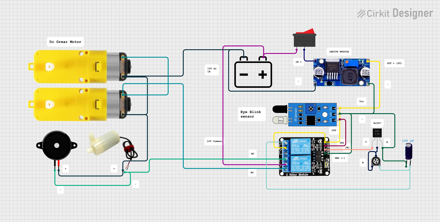
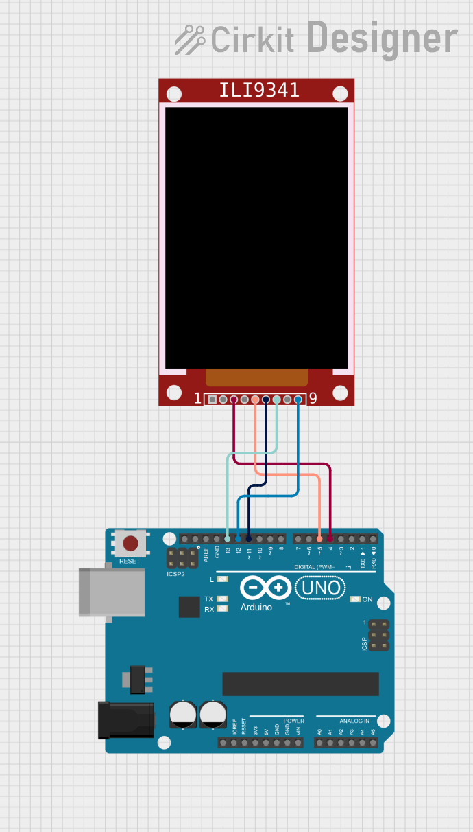
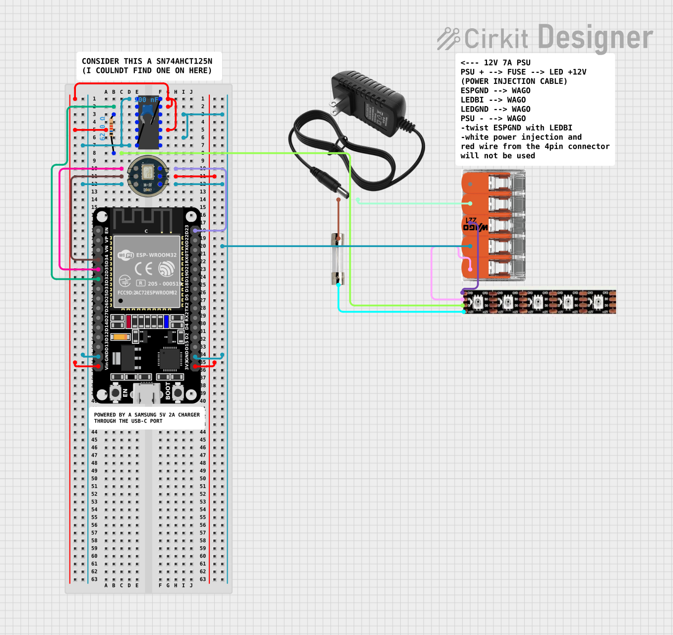
Explore Projects Built with iwrl6432 spem
Technical Specifications
The IWRL6432 SPEM is engineered to deliver robust performance while maintaining low power consumption. Below are the key technical details:
General Specifications
| Parameter | Value |
|---|---|
| Manufacturer | Texas Instruments |
| Part ID | SPEM |
| Wireless Protocols | Zigbee, Bluetooth Low Energy |
| Operating Voltage | 1.8V to 3.6V |
| Operating Temperature | -40°C to 85°C |
| Frequency Range | 2.4 GHz |
| Data Rate | Up to 2 Mbps |
| Power Consumption | 5 µA (sleep mode), 15 mA (TX) |
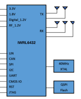
Pin Configuration
The IWRL6432 SPEM module features a 16-pin layout. Below is the pin configuration and description:
| Pin Number | Pin Name | Description |
|---|---|---|
| 1 | VCC | Power supply input (1.8V to 3.6V) |
| 2 | GND | Ground |
| 3 | TXD | UART Transmit Data |
| 4 | RXD | UART Receive Data |
| 5 | GPIO1 | General-purpose I/O pin |
| 6 | GPIO2 | General-purpose I/O pin |
| 7 | RESET | Active-low reset pin |
| 8 | ANT | Antenna connection |
| 9 | SCL | I2C Clock |
| 10 | SDA | I2C Data |
| 11 | SPI_MOSI | SPI Master Out Slave In |
| 12 | SPI_MISO | SPI Master In Slave Out |
| 13 | SPI_CLK | SPI Clock |
| 14 | SPI_CS | SPI Chip Select |
| 15 | ADC_IN | Analog-to-Digital Converter input |
| 16 | PWM_OUT | Pulse Width Modulation output |
Usage Instructions
To use the IWRL6432 SPEM in a circuit, follow these steps:
- Power Supply: Connect the VCC pin to a stable power source within the range of 1.8V to 3.6V. Connect the GND pin to the ground of your circuit.
- Communication Interface: Choose the appropriate communication protocol (UART, I2C, or SPI) based on your application. Connect the corresponding pins (e.g., TXD/RXD for UART, SCL/SDA for I2C, or SPI_MOSI/SPI_MISO/SPI_CLK/SPI_CS for SPI).
- Antenna: Attach a compatible 2.4 GHz antenna to the ANT pin for wireless communication.
- GPIO and ADC: Use the GPIO pins for general-purpose input/output tasks and the ADC_IN pin for analog signal input.
- Reset: Connect the RESET pin to a microcontroller or a manual reset button for module initialization.
Important Considerations
- Ensure proper decoupling capacitors are placed near the VCC pin to stabilize the power supply.
- Use a low-impedance ground plane to minimize noise and improve signal integrity.
- For optimal wireless performance, position the antenna away from metal objects and other sources of interference.
- Avoid exceeding the maximum voltage ratings to prevent damage to the module.
Example: Connecting to an Arduino UNO
The IWRL6432 SPEM can be easily interfaced with an Arduino UNO using the UART interface. Below is an example code snippet to send and receive data:
// IWRL6432 SPEM Example: UART Communication with Arduino UNO
// Connect TXD (Pin 3) of IWRL6432 to RX (Pin 0) of Arduino
// Connect RXD (Pin 4) of IWRL6432 to TX (Pin 1) of Arduino
// Ensure proper power and ground connections

void setup() {
  Serial.begin(9600); // Initialize UART communication at 9600 baud rate
  Serial.println("IWRL6432 SPEM Initialized"); // Send initialization message
}

void loop() {
  if (Serial.available() > 0) {
    // Read data from the IWRL6432 module
    String receivedData = Serial.readString();
    Serial.print("Received: ");
    Serial.println(receivedData); // Print received data to Serial Monitor
  }

  // Send data to the IWRL6432 module
  Serial.println("Hello, IWRL6432!");
  delay(1000); // Wait for 1 second before sending the next message
}
Troubleshooting and FAQs
Common Issues
No Communication with the Module
- Solution: Verify the connections for the communication interface (UART, I2C, or SPI). Ensure the correct pins are connected and the baud rate or protocol settings match.
Poor Wireless Range
- Solution: Check the antenna connection and ensure it is properly positioned. Avoid placing the module near metal objects or other sources of interference.
Module Not Powering On
- Solution: Confirm that the VCC pin is receiving a stable voltage within the specified range (1.8V to 3.6V). Check for loose connections or damaged wires.
Unstable Data Transmission
- Solution: Use proper decoupling capacitors near the power supply pins. Ensure the ground plane is low-impedance and free from noise.
FAQs
Can the IWRL6432 SPEM operate on a 5V power supply?
- No, the module operates within a voltage range of 1.8V to 3.6V. Using a 5V supply may damage the module.
What is the maximum data rate supported by the module?
- The IWRL6432 SPEM supports data rates of up to 2 Mbps.
Is the module compatible with both Zigbee and Bluetooth?
- Yes, the module supports both Zigbee and Bluetooth Low Energy protocols, making it versatile for various applications.
Can I use the module in outdoor environments?
- Yes, the module is designed to operate within a temperature range of -40°C to 85°C, making it suitable for outdoor use in most conditions.
By following this documentation, users can effectively integrate the IWRL6432 SPEM into their projects and troubleshoot common issues with ease.